Terminals Of Ecu [11/2023 - ]
- CHECK POWER DISTRIBUTION BOX ASSEMBLY AND MAIN BODY ECU (MULTIPLEX NETWORK BODY ECU)
- Remove the main body ECU (multiplex network body ECU) from the power distribution box assembly.
Refer to REMOVAL [11/2023 - ]
- Reconnect the power distribution box assembly connectors.
- Measure the resistance and voltage according to the value(s) in the table below.
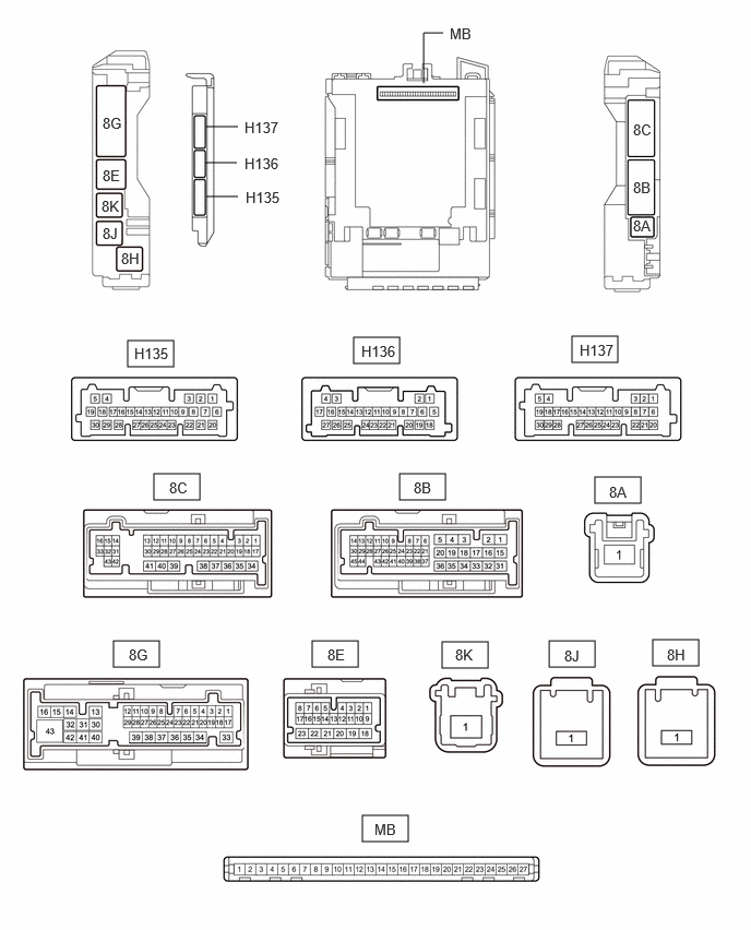
Terminal No. (Symbol) Terminal Description Condition Specified Condition MB-13 (GND1) - Body ground Ground Always Below 1 Ω MB-14 (GND2) - Body ground Ground Always Below 1 Ω MB-26 (BECU) - Body ground Auxiliary battery power supply Ignition switch off 11 to 14 V MB-27 (IGR) - Body ground Ignition power supply (IG signal) Ignition switch off Below 1 V Ignition switch ON 11 to 14 V - Install the main body ECU (multiplex network body ECU) to power distribution box assembly.
Refer to INSTALLATION [11/2023 - ]
- Measure the voltage and check for pulses according to the value(s) in the table below.
Terminal No. (Symbol) Terminal Description Condition Specified Condition 8G-3 (FLCY) - Body ground Front door courtesy light switch assembly (LH) input Front door LH open → closed Below 1 V → 11 to 14 V or pulse output (maximum 14 V)*1 8C-9 (FRCY) - Body ground Front door courtesy light switch assembly (RH) input Front door RH open → closed Below 1 V → 11 to 14 V or pulse output (maximum 14 V)*1 8G-26 (LCTY) - Body ground Rear door courtesy light switch assembly (LH) input Rear door LH open → closed Below 1 V → 11 to 14 V or pulse output (maximum 14 V)*1 8G-1 (RCTY) - Body ground Rear door courtesy light switch assembly (RH) input Rear door RH open → closed Below 1 V → 11 to 14 V or pulse output (maximum 14 V)*1 8G-2 (BCTY) - Body ground Back door courtesy light switch input Back door open → closed Below 1 V → 11 to 14 V or pulse output (maximum 14 V)*1 H135-9 (LSFL) - Body ground Front door LH unlock detection switch input Front door LH unlocked → locked Below 1 V → 11 to 14 V or pulse output (maximum 14 V)*1 H135-3 (LSFR) - Body ground Front door RH unlock detection switch input Front door RH unlocked → locked Below 1 V → 11 to 14 V or pulse output (maximum 14 V)*1 H135-10 (LSWL) - Body ground Rear door LH unlock detection switch input Rear door LH unlocked → locked Below 1 V → 11 to 14 V or pulse output (maximum 14 V)*1 H136-23 (LSWR) - Body ground Rear door RH unlock detection switch input Rear door RH unlocked → locked Below 1 V → 11 to 14 V or pulse output (maximum 14 V)*1 8G-36 (ACT-) - Body ground Door lock motor unlock drive output Door control switch or driver door key cylinder off → on (unlock) Below 1 V → 11 to 14 V → Below 1 V 8G-37 (ACT-) - Body ground Door lock motor unlock drive output Door control switch or driver door key cylinder off → on (unlock) Below 1 V → 11 to 14 V → Below 1 V 8C-36 (ACT-) - Body ground Door lock motor unlock drive output Door control switch or driver door key cylinder off → on (unlock) Below 1 V → 11 to 14 V → Below 1 V 8G-14 (ACT+) - Body ground Door lock motor lock drive output Door control switch or driver door key cylinder off → on (lock) Below 1 V → 11 to 14 V → Below 1 V 8G-15 (ACT+) - Body ground Door lock motor lock drive output Door control switch or driver door key cylinder off → on (lock) Below 1 V → 11 to 14 V → Below 1 V 8B-19 (ACT+) - Body ground Door lock motor lock drive output Door control switch or driver door key cylinder off → on (lock) Below 1 V → 11 to 14 V → Below 1 V 8B-20 (ACTD) - Body ground Door lock motor unlock drive output Door control switch or driver door key cylinder off → on (unlock) Below 1 V → 11 to 14 V → Below 1 V 8G-39 (TR+) - Body ground*2 Back door lock motor unlock drive output Back door closed → open Below 1 V → 11 to 14 V → Below 1 V H135-4 (UL3) - Body ground Driver door key-linked unlock input Driver door key cylinder in neutral position → on (unlock) Pulse generation → Below 1 V H135-28 (L2) - Body ground Driver door key-linked lock input Driver door key cylinder in neutral position → on (lock) Pulse generation → Below 1 V H136-6 (L1) - Body ground Door control switch assembly input Door control switch assembly off → on (lock) Pulse generation → Below 1 V H136-7 (UL1) - Body ground Door control switch assembly input Door control switch assembly off → on (unlock) Pulse generation → Below 1 V 8C-43 (GSW) - Body ground Airbag ECU signal (collision detection signal) Ignition switch ON with airbag ECU assembly connector disconnected 4.3 to 5.5 V - *1: Differs depending on the vehicle model
- *2: w/o Power Back Door System
- Remove the main body ECU (multiplex network body ECU) from the power distribution box assembly.
- CHECK CERTIFICATION ECU (SMART KEY ECU ASSEMBLY) (w/ Smart Key System)
Refer to TERMINALS OF ECU [11/2023 - ]
- CHECK AIRBAG SENSOR ASSEMBLY
Refer to TERMINALS OF ECU [11/2023 - ]