DTC B2271: Ignition Hold Monitor Malfunction [12/2019 - 11/2023]: Procedure
- CHECK HARNESS AND CONNECTOR (POWER SOURCE)
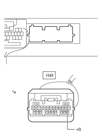
- Disconnect the H48 certification ECU (smart key ECU assembly) connector.
*a Front view of wire harness connector
(to Certification ECU (Smart Key ECU Assembly)) - Measure the voltage according to the value(s) in the table below.
Standard Voltage
Tester Connection Condition Specified Condition H48-4 (+B) - Body ground Always 11 to 14 V Result
Proceed to OK NG
Result:
NG
REPAIR OR REPLACE HARNESS OR CONNECTOR IN CIRCUIT CONNECTED TO POWER SOURCE
Result:
OK
See step 2
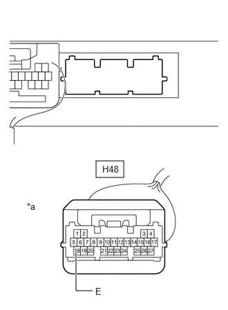
- Disconnect the H48 certification ECU (smart key ECU assembly) connector.
- CHECK HARNESS AND CONNECTOR (GROUND)
- Measure the resistance according to the value(s) in the table below.
Standard Resistance
Tester Connection Condition Specified Condition H48-18 (E) - Body ground Always Below 1 Ω *a Front view of wire harness connector
(to Certification ECU (Smart Key ECU Assembly))Result
Proceed to OK NG
Result:
NG
REPAIR OR REPLACE HARNESS OR CONNECTOR
Result:
OK
See step 3
- Measure the resistance according to the value(s) in the table below.
- CHECK HARNESS AND CONNECTOR (CERTIFICATION ECU (SMART KEY ECU ASSEMBLY) - INSTRUMENT PANEL JUNCTION BLOCK ASSEMBLY)
- Disconnect the 4A instrument panel junction block assembly connector.
- Measure the resistance according to the value(s) in the table below.
Standard Resistance
Tester Connection Condition Specified Condition H48-17 (IG1D) - 4A-17 Always Below 1 Ω H48-17 (IG1D) or 4A-17 - Other terminals and body ground Always 10 kΩ or higher Result
Proceed to OK NG
Result:
NG
REPAIR OR REPLACE HARNESS OR CONNECTOR
Result:
OK
See step 4
- INSPECT INSTRUMENT PANEL JUNCTION BLOCK ASSEMBLY
- Disconnect the 4C instrument panel junction block assembly connector.
- Measure the resistance according to the value(s) in the table below.
Standard Resistance
Tester Connection Condition Specified Condition 4A-17 - 4C-12 Always Below 1 Ω 4A-17 or 4C-12 - Other terminals Always 10 kΩ or higher Result
Proceed to OK NG
Result:
NG
REPLACE INSTRUMENT PANEL JUNCTION BLOCK ASSEMBLY. Refer to REMOVAL [12/2019 - 10/2022] , or refer to REMOVAL [10/2022 - 11/2023]
Result:
OK
See step 5
- CHECK HARNESS AND CONNECTOR (INSTRUMENT PANEL JUNCTION BLOCK ASSEMBLY - IG2 NO. 1 RELAY)
- Remove the IG2 NO. 1 relay from the No. 1 engine room relay block and No. 1 junction block assembly.
- Measure the resistance according to the value(s) in the table below.
Standard Resistance
Tester Connection Condition Specified Condition 4C-12 - No. 1 engine room relay block and No. 1 junction block assembly IG2 NO. 1 relay terminal 1 Always Below 1 Ω 4C-12 or No. 1 engine room relay block and No. 1 junction block assembly IG2 NO. 1 terminal 1 - Other terminals and body ground Always 10 kΩ or higher Result
Proceed to OK NG
Result:
NG
REPAIR OR REPLACE HARNESS OR CONNECTOR
Result:
OK
See step 6
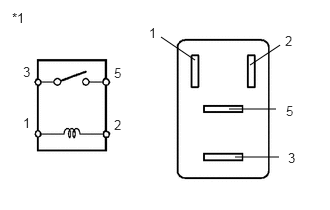
- INSPECT IG2 NO. 1 RELAY
- Measure the resistance according to the value(s) in the table below.
Standard Resistance
Tester Connection Condition Specified Condition 3 - 5 Battery voltage not applied between terminals 1 and 2 10 kΩ or higher 3 - 5 Battery voltage applied between terminals 1 and 2 Below 1 Ω *1 IG2 NO. 1 Relay Result
Proceed to OK NG
Result:
NG
REPLACE IG2 NO. 1 RELAY
Result:
OK
See step 7
- Measure the resistance according to the value(s) in the table below.
- INSPECT INSTRUMENT PANEL JUNCTION BLOCK ASSEMBLY
- Disconnect the 4B instrument panel junction block assembly connector.
- Measure the resistance according to the value(s) in the table below.
Standard Resistance
Tester Connection Condition Specified Condition 4A-17 - 4B-3 Always 20 Ω or higher 4A-17 or 4B-3 - Other terminals Always 10 kΩ or higher Result
Proceed to OK NG
Result:
OK
REPLACE CERTIFICATION ECU (SMART KEY ECU ASSEMBLY). Refer to REMOVAL [12/2019 - 11/2023]
Result:
NG
REPLACE INSTRUMENT PANEL JUNCTION BLOCK ASSEMBLY. Refer to REMOVAL [12/2019 - 10/2022] , or refer to REMOVAL [10/2022 - 11/2023]