DTC B2271-11: IG Circuit Short to Ground [11/2023 - ]: Procedure
- CHECK HARNESS AND CONNECTOR (POWER SOURCE)
Pre-procedure1
- Disconnect the H138 certification ECU (smart key ECU assembly) connector.
Procedure1
- Measure the voltage according to the value(s) in the table below.
Standard Voltage
Tester Connection Condition Specified Condition H138-6 (+B) - Body ground Ignition switch off 11 to 14 V Result
Proceed to OK NG Post-procedure1
- None
Result:
NG
REPAIR OR REPLACE HARNESS OR CONNECTOR IN CIRCUIT CONNECTED TO POWER SOURCE
Result:
OK
See step 2
- Disconnect the H138 certification ECU (smart key ECU assembly) connector.
- CHECK HARNESS AND CONNECTOR (GROUND)
- Measure the resistance according to the value(s) in the table below.
Standard Resistance
Tester Connection Condition Specified Condition H138-29 (E) - Body ground Always Below 1 Ω Result
Proceed to OK NG
Result:
NG
REPAIR OR REPLACE HARNESS OR CONNECTOR
Result:
OK
See step 3
- Measure the resistance according to the value(s) in the table below.
- CHECK HARNESS AND CONNECTOR (POWER DISTRIBUTION BOX ASSEMBLY - CERTIFICATION ECU (SMART KEY ECU ASSEMBLY) AND BODY GROUND)
Pre-procedure1
- Disconnect the A88 certification ECU (smart key ECU assembly) connector.
- Disconnect the 8B and 8C power distribution box assembly connectors.
Procedure1
- Measure the resistance according to the value(s) in the table below.
Standard Resistance
Tester Connection Condition Specified Condition 8C-17 - A88-24 (IGPD) Always Below 1 Ω 8B-11 - A88-11 (IGRD) Always Below 1 Ω 8C-17 or A88-24 (IGPD) - Other terminals and body ground Always 10 kΩ or higher 8B-11 or A88-11 (IGRD) - Other terminals and body ground Always 10 kΩ or higher Result
Proceed to OK NG Post-procedure1
- None
Result:
NG
REPAIR OR REPLACE HARNESS OR CONNECTOR
Result:
OK
See step 4
- CHECK POWER DISTRIBUTION BOX ASSEMBLY
Pre-procedure1
- Disconnect the 8E power distribution box assembly connector.
Procedure1
- Measure the resistance according to the value(s) in the table below.
Standard Resistance
Tester Connection Condition Specified Condition 8C-17 - 8E-13 Always Below 1 Ω 8C-17 or 8E-13 - Other terminals Always 10 kΩ or higher Result
Proceed to OK NG Post-procedure1
- None
Result:
NG
REPLACE POWER DISTRIBUTION BOX ASSEMBLY. Refer to REMOVAL [11/2023 - ]
Result:
OK
See step 5
- Disconnect the 8E power distribution box assembly connector.
- CHECK HARNESS AND CONNECTOR (POWER DISTRIBUTION BOX ASSEMBLY - IGP NO. 1 RELAY)
Pre-procedure1
- Remove the IGP NO. 1 relay from the No. 1 engine room relay block and No. 1 junction block assembly.
Procedure1
- Measure the resistance according to the value(s) in the table below.
Standard Resistance
Tester Connection Condition Specified Condition 8E-13 - IGP NO. 1 relay terminal 1 Always Below 1 Ω 8E-13 or IGP NO. 1 relay terminal 1 - Other terminals and body ground Always 10 kΩ or higher Result
Proceed to OK NG Post-procedure1
- None
Result:
NG
REPAIR OR REPLACE HARNESS OR CONNECTOR
Result:
OK
See step 6
- Remove the IGP NO. 1 relay from the No. 1 engine room relay block and No. 1 junction block assembly.
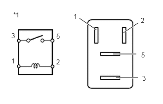
- INSPECT IGP NO. 1 RELAY
- Measure the resistance according to the value(s) in the table below.
Standard Resistance
Tester Connection Condition Specified Condition 3 - 5 Auxiliary battery voltage applied between terminals 1 and 2 Below 1 Ω 3 - 5 Auxiliary battery voltage not applied between terminals 1 and 2 10 kΩ or higher *1 IGP NO. 1 Relay Result
Proceed to OK NG
Result:
NG
REPLACE IGP NO. 1 RELAY
Result:
OK
See step 7
- Measure the resistance according to the value(s) in the table below.
- CHECK POWER DISTRIBUTION BOX ASSEMBLY
- Measure the resistance according to the value(s) in the table below.
Standard Resistance
Tester Connection Condition Specified Condition 8B-11 - 8B-36 Always 20 Ω or higher 8B-11 - 8C-41 Always 20 Ω or higher 8B-11 or 8B-36 - Other terminals Always 10 kΩ or higher 8B-11 or 8C-41 - Other terminals Always 10 kΩ or higher Result
Proceed to OK NG
Result:
OK
REPLACE CERTIFICATION ECU (SMART KEY ECU ASSEMBLY). Refer to REMOVAL [11/2023 - ]
Result:
NG
REPLACE POWER DISTRIBUTION BOX ASSEMBLY. Refer to REMOVAL [11/2023 - ]
- Measure the resistance according to the value(s) in the table below.