DTC B2282: Vehicle Speed Signal Malfunction; DTC B2283: Vehicle Speed Sensor Malfunction [10/2022 - 11/2023]: Procedure
- READ VALUE USING GTS (VEHICLE SPEED METER)
- Read the Data List according to the display on the GTS.
Body Electrical > Combination Meter > Data List
Tester Display Measurement Item Range Normal Condition Diagnostic Note Vehicle Speed Meter Vehicle speed Min.: 0, Max.: 255 Almost same as actual vehicle speed (Speedometer tester) - Body Electrical > Combination Meter > Data List
Tester Display Vehicle Speed Meter HINT:
Using a speedometer tester, check the actual vehicle speed and the vehicle speed displayed on the GTS.
OK
Vehicle speed displayed on the GTS is almost the same as the actual vehicle speed measured using a speedometer tester.
Result
Proceed to OK NG
Result:
NG
GO TO METER / GAUGE SYSTEM (Speedometer Malfunction)
for 12.3 Inch Display: Refer to Speedometer Malfunction [10/2022 - ]
except 12.3 Inch Display: Refer to Speedometer Malfunction [12/2019 - ]
Result:
OK
See step 2
- Read the Data List according to the display on the GTS.
- READ VALUE USING GTS (VEHICLE SPEED SIGNAL)
- Read the Data List according to the display on the GTS.
Body Electrical > Power Source Control > Data List
Tester Display Measurement Item Range Normal Condition Diagnostic Note Vehicle Speed Signal Vehicle being driven or stopped Stop or Run Stop: Vehicle stopped
Run: Vehicle being driven at 5 km/h (3 mph) or more- Body Electrical > Power Source Control > Data List
Tester Display Vehicle Speed Signal OK
The GTS display changes correctly in response to the vehicle condition.
Result
Proceed to OK NG
Result:
OK
GO TO METER / GAUGE SYSTEM (HOW TO PROCEED WITH TROUBLESHOOTING)
for 12.3 Inch Display: Refer to HOW TO PROCEED WITH TROUBLESHOOTING [10/2022 - ]
except 12.3 Inch Display: Refer to HOW TO PROCEED WITH TROUBLESHOOTING [12/2019 - ]
Result:
NG
See step 3
- Read the Data List according to the display on the GTS.
- CHECK HARNESS AND CONNECTOR (CERTIFICATION ECU (SMART KEY ECU ASSEMBLY) - COMBINATION METER ASSEMBLY)
- Disconnect the H112*1 or H21*2 combination meter assembly connector.
- *1: for 12.3 Inch Display
- *2: except 12.3 Inch Display
- Disconnect the H48 certification ECU (smart key ECU assembly) connector.
- Disconnect the A83 ECM connector.
- Disconnect the H107 radio and display receiver assembly connector.
- Disconnect the M38 stereo component amplifier assembly connector.
- Measure the resistance according to the value(s) in the table below.
Standard Resistance
FOR 12.3 INCH DISPLAY:Tester Connection Condition Specified Condition H48-19 (SPD) - H107-8 (+S) Always Below 1 Ω H48-19 (SPD) or H107-8 (+S) - Other terminals and body ground Always 10 kΩ or higher EXCEPT 12.3 INCH DISPLAY:Tester Connection Condition Specified Condition H48-19 (SPD) - H21-6 (+S) Always Below 1 Ω H48-19 (SPD) or H21-6 (+S) - Other terminals and body ground Always 10 kΩ or higher Result
Proceed to OK NG
Result:
NG
REPAIR OR REPLACE HARNESS OR CONNECTOR
Result:
OK
See step 4
- Disconnect the H112*1 or H21*2 combination meter assembly connector.
- CHECK CERTIFICATION ECU (SMART KEY ECU ASSEMBLY)
- Connect the H48 certification ECU (smart key ECU assembly) connector.
- Connect the H112*1 or H21*2 combination meter assembly connector.
- *1: for 12.3 Inch Display
- *2: except 12.3 Inch Display
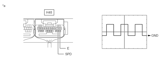
- Using an oscilloscope, check the waveform.
*a Component with harness connected
(Certification ECU (Smart Key ECU Assembly))- - Tester Connection Condition Tool Setting Specified Condition H48-19 (SPD) - H48-18 (E) Ignition switch ON, vehicle being driven at approx. 5 km/h (3 mph) 5 V/DIV., 20 ms./DIV. Pulse generation HINT:
The wavelength becomes shorter as the vehicle speed increases.
Result
Proceed to OK NG
Result:
OK
REPLACE CERTIFICATION ECU (SMART KEY ECU ASSEMBLY). Refer to REMOVAL [12/2019 - 11/2023]
Result:
NG
GO TO METER / GAUGE SYSTEM (Speed Signal Circuit)
for 12.3 Inch Display: Refer to Speed Signal Circuit [10/2022 - 11/2023]
except 12.3 Inch Display: Refer to Speed Signal Circuit [10/2022 - 11/2023]