DTC B2788: IG2 Signal Malfunction [12/2019 - 10/2021]: Procedure
- CHECK HARNESS AND CONNECTOR (POWER SOURCE)
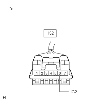
- Disconnect the H52 steering lock ECU (steering lock actuator or upper bracket assembly) connector.
- Measure the voltage according to the value(s) in the table below.
*a Front view of wire harness connector
(to Steering Lock ECU (Steering Lock Actuator or Upper Bracket Assembly))Standard Voltage
Tester Connection Condition Specified Condition H52-6 (IG2) - Body ground Ignition switch ON 11 to 14 V H52-6 (IG2) - Body ground Ignition switch off Below 1 V Result
Proceed to OK NG
Result:
NG
REPAIR OR REPLACE HARNESS OR CONNECTOR
Result:
OK
See step 2
- CHECK HARNESS AND CONNECTOR (GROUND)
- Measure the resistance according to the value(s) in the table below.
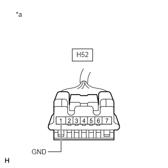
*a Front view of wire harness connector
(to Steering Lock ECU (Steering Lock Actuator or Upper Bracket Assembly))Standard Resistance
Tester Connection Condition Specified Condition H52-1 (GND) - Body ground Always Below 1 Ω Result
Proceed to OK NG
Result:
OK
REPLACE STEERING LOCK ECU (STEERING LOCK ACTUATOR OR UPPER BRACKET ASSEMBLY). Refer to DISASSEMBLY [12/2019 - 10/2021]
Result:
NG
REPAIR OR REPLACE HARNESS OR CONNECTOR
- Measure the resistance according to the value(s) in the table below.