DTC P0571-62: Brake Switch "A" Signal Compare Failure [11/2023 - ]: Procedure
- READ VALUE USING GTS (STOP LIGHT SWITCH)
- Read the Data List according to the display on the GTS.
Body Electrical > Power Source Control > Data List
Tester Display Measurement Item Range Normal Condition Diagnostic Note Stop Light Switch State of brake pedal OFF or ON OFF: Brake pedal released - Use this item to determine if the stop light switch assembly is malfunctioning.
- The engine cannot be started when this item is OFF.
- If the stop light switch assembly is malfunctioning, the engine can be started by pressing and holding the engine switch for a certain period of time.
Body Electrical > Power Source Control > Data List
Tester Display Stop Light Switch OK
The GTS display changes correctly in response to the brake pedal operation.
Result
Result Proceed to The value of Stop Light Switch is OFF A The value of Stop Light Switch is not OFF B
Result:
B
See step 3
Result:
A
See step 2
- Read the Data List according to the display on the GTS.
- READ VALUE USING GTS (STOP LIGHT SWITCH)
- Read the Data List according to the display on the GTS.
Body Electrical > Power Source Control > Data List
Tester Display Measurement Item Range Normal Condition Diagnostic Note Stop Light Switch State of brake pedal OFF or ON ON: Brake pedal depressed - Use this item to determine if the stop light switch assembly is malfunctioning.
- The engine cannot be started when this item is OFF.
- If the stop light switch assembly is malfunctioning, the engine can be started by pressing and holding the engine switch for a certain period of time.
Body Electrical > Power Source Control > Data List
Tester Display Stop Light Switch OK
The GTS display changes correctly in response to the brake pedal operation.
Result
Result Proceed to The value of Stop Light Switch is ON A The value of Stop Light Switch is not ON B
Result:
A
GO TO ELECTRONICALLY CONTROLLED BRAKE SYSTEM (HOW TO PROCEED WITH TROUBLESHOOTING). Refer to HOW TO PROCEED WITH TROUBLESHOOTING [11/2023 - ]
Result:
B
See step 3
- Read the Data List according to the display on the GTS.
- CHECK HARNESS AND CONNECTOR (CERTIFICATION ECU (SMART KEY ECU ASSEMBLY) - STOP LIGHT SWITCH ASSEMBLY)
Pre-procedure1
- Disconnect the A88 certification ECU (smart key ECU assembly) connector.
- Disconnect the A42 stop light switch assembly connector.
- Disconnect the A39 skid control ECU (brake actuator assembly) connector.
- Disconnect the A83 ECM connector.
Procedure1
- Measure the resistance according to the value(s) in the table below.
Standard Resistance
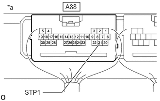
Tester Connection Condition Specified Condition A88-21 (STP1) - A42-3 (L) Always Below 1 Ω Result
Proceed to OK NG Post-procedure1
- None
Result:
NG
REPAIR OR REPLACE HARNESS OR CONNECTOR
Result:
OK
See step 4
- CHECK CERTIFICATION ECU (SMART KEY ECU ASSEMBLY)
Pre-procedure1
- Connect the A88 certification ECU (smart key ECU assembly) connector.
- Connect the A42 stop light switch assembly connector.
Procedure1
- Measure the voltage according to the value(s) in the table below.
*a Component with harness connected
(Certification ECU (Smart Key ECU Assembly))Standard Voltage
Tester Connection Condition Specified Condition A88-21 (STP1) - Body ground Brake pedal released 1 V or less A88-21 (STP1) - Body ground Brake pedal depressed 9 V or higher Result
Proceed to OK NG Post-procedure1
- None
Result:
OK
REPLACE CERTIFICATION ECU (SMART KEY ECU ASSEMBLY). Refer to REMOVAL [11/2023 - ]
Result:
NG
REPLACE STOP LIGHT SWITCH ASSEMBLY. Refer to REMOVAL [12/2019 - ]