Security Indicator Light Does not Blink [12/2019 - 11/2023]: Procedure
- CHECK FOR DTC
- Check for DTCs.
Body Electrical > Smart Key > Trouble Codes
Powertrain > Engine > Trouble Codes
OK
DTCs are not output.
Result
Proceed to OK NG
Result:
NG
GO TO DIAGNOSTIC TROUBLE CODE CHART. Refer to DIAGNOSTIC TROUBLE CODE CHART [12/2019 - 10/2021] , or refer to DIAGNOSTIC TROUBLE CODE CHART [10/2021 - 10/2022] , or refer to DIAGNOSTIC TROUBLE CODE CHART [10/2022 - 11/2023]
Result:
OK
See step 2
- Check for DTCs.
- PERFORM ACTIVE TEST USING GTS (IMMOBILIZER INDICATOR)
- Perform the Active Test according to the display on the GTS.
Body Electrical > Smart Key > Active Test
Tester Display Measurement Item Control Range Diagnostic Note Immobilizer Indicator Security indicator light OFF/ON - Body Electrical > Smart Key > Active Test
Tester Display Immobilizer Indicator OK
The security indicator light (radio receiver assembly) operates normally.
Result
Proceed to OK NG
Result:
NG
See step 4
Result:
OK
See step 3
- Perform the Active Test according to the display on the GTS.
- CHECK SECURITY INDICATOR LIGHT (TELLTALE LIGHT ASSEMBLY) OPERATION
- When the immobilizer is set, check that the security indicator light (telltale light assembly) blinks.*1
OK
The security indicator light (telltale light assembly) blinks normally.
- When the theft deterrent system is in the arming preparation state, check that the security indicator light (telltale light assembly) illuminates.*2
OK
The security indicator light (telltale light assembly) illuminates normally.
Result
Result Proceed to *1 is NG (*2 is OK) A *2 is NG (*1 is OK) B
Result:
A
REPLACE CERTIFICATION ECU (SMART KEY ECU ASSEMBLY). Refer to REMOVAL [12/2019 - 11/2023]
Result:
B
REPLACE MAIN BODY ECU (MULTIPLEX NETWORK BODY ECU). Refer to REMOVAL [12/2019 - 10/2022] , or refer to REMOVAL [10/2022 - 11/2023]
- When the immobilizer is set, check that the security indicator light (telltale light assembly) blinks.*1
- CHECK HARNESS AND CONNECTOR (CERTIFICATION ECU (SMART KEY ECU ASSEMBLY) - SECURITY INDICATOR LIGHT (TELLTALE LIGHT ASSEMBLY) AND BODY GROUND)
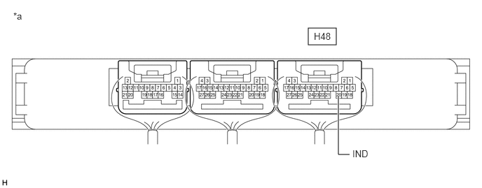
- Disconnect the H48 certification ECU (smart key ECU assembly) connector.
- Disconnect the H33 security indicator light (telltale light assembly) connector.
- Measure the resistance according to the value(s) in the table below.
Standard Resistance
Tester Connection Condition Specified Condition H48-20 (IND) - H33-3 (LP) Always Below 1 Ω H48-20 (IND) or H33-3 (LP) - Other terminals and body ground Always 10 kΩ or higher H33-4 (E) - Body ground Always Below 1 Ω Result
Proceed to OK NG
Result:
NG
REPAIR OR REPLACE HARNESS OR CONNECTOR
Result:
OK
See step 5
- CHECK CERTIFICATION ECU (SMART KEY ECU ASSEMBLY)
- Connect the H48 certification ECU (smart key ECU assembly) connector.
- Connect the H33 security indicator light (telltale light assembly) connector.
- Using an oscilloscope, check the waveform.
*a Component with harness connected
(Certification ECU (Smart Key ECU Assembly))- - Measurement Condition
Tester Connection Condition Specified Condition H48-20 (IND) - Body ground Ignition switch off → ON Pulse generation → Below 2 V Result
Proceed to OK NG
Result:
OK
REPLACE SECURITY INDICATOR LIGHT (TELLTALE LIGHT ASSEMBLY). Refer to REMOVAL [12/2019 - 10/2022] , or refer to REMOVAL [10/2022 - ]
Result:
NG
REPLACE CERTIFICATION ECU (SMART KEY ECU ASSEMBLY). Refer to REMOVAL [12/2019 - 11/2023]