Terminals Of Ecu [12/2019 - 11/2023]
- CHECK MAIN BODY ECU (MULTIPLEX NETWORK BODY ECU) AND INSTRUMENT PANEL JUNCTION BLOCK ASSEMBLY
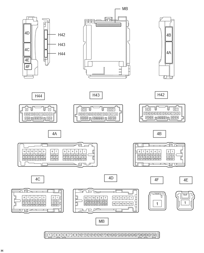
- Remove the main body ECU (multiplex network body ECU) from the instrument panel junction block assembly.
Refer to REMOVAL [12/2019 - 10/2022] , or refer to REMOVAL [10/2022 - 11/2023]
- Reconnect the instrument panel junction block assembly connectors.
- Measure the resistance and voltage according to the value(s) in the table below.
Terminal No. (Symbol) Terminal Description Condition Specified Condition MB-31 (BECU) - Body ground Auxiliary battery power supply Ignition switch off*1
Always*211 to 14 V MB-32 (IG) - Body ground Ignition power supply (IG signal) Ignition switch off Below 1 V Ignition switch ON 11 to 14 V MB-30 (ACC) - Body ground Ignition power supply (ACC signal) Ignition switch off Below 1 V Ignition switch ACC 11 to 14 V MB-11 (GND1) - Body ground Ground Always Below 1 Ω H42-19 (GND2) - Body ground Ground Always Below 1 Ω H43-1 (FLCY) - Body ground Front door courtesy light switch assembly (for LH) input Front door LH closed 10 kΩ or higher Front door LH open Below 1 Ω H43-6 (FRCY) - Body ground Front door courtesy light switch assembly (for RH) input Front door RH closed 10 kΩ or higher Front door RH open Below 1 Ω MB-13 (LCTY) - Body ground Rear door courtesy light switch assembly (for LH) input Rear door LH closed 10 kΩ or higher Rear door LH open Below 1 Ω MB-2 (RCTY) - Body ground Rear door courtesy light switch assembly (for RH) input Rear door RH closed 10 kΩ or higher Rear door RH open Below 1 Ω H43-30 (HCTY) - Body ground Engine hood courtesy switch input Engine hood open 10 kΩ or higher Engine hood closed Below 1 Ω MB-4 (BCTY) - Body ground Back door courtesy light switch input Back door closed 10 kΩ or higher Back door open Below 1 Ω MB-14 (TRLY) - Body ground Taillight relay drive output Ignition switch off 11 to 14 V - *1: for HV Model
- *2: for Gasoline Model
- Install the main body ECU (multiplex network body ECU) to instrument panel junction block assembly.
Refer to INSTALLATION [12/2019 - 10/2022] , or refer to INSTALLATION [10/2022 - 11/2023]
- Measure the voltage and check for pulses according to the value(s) in the table below.
Terminal No. (Symbol) Terminal Description Condition Specified Condition 4B-13 (LSFL) - Body ground Front door LH unlock detection switch input Front door LH unlocked Below 1 V Front door LH locked 11 to 14 V 4B-12 (LSFR) - Body ground Front door RH unlock detection switch input Front door RH unlocked Below 1 V Front door RH locked 11 to 14 V H44-18 (L2) - Body ground Driver door key-linked lock input Driver door key cylinder turned to lock position Below 1 V Driver door key cylinder off 11 to 14 V H44-17 (UL3) - Body ground Driver door key-linked unlock input Driver door key cylinder turned to unlock position Below 1 V Driver door key cylinder off 11 to 14 V 4B-14 (LSWL) - Body ground Rear door LH unlock detection switch input Rear door LH unlocked Below 1 V Rear door LH locked 11 to 14 V H43-17 (LSWR) - Body ground Rear door RH unlock detection switch input Rear door RH unlocked Below 1 V Rear door RH locked 11 to 14 V 4A-20 (SH) - Body ground Security horn assembly drive Security horn assembly sounding
(Theft deterrent system in alarm sounding state)Pulse generation
(Below 1 V ← → 11 to 14 V)4C-27 (HORN) - Body ground Vehicle horn drives Vehicle horn sounding
(Theft deterrent system in alarm sounding state)Pulse generation
(Below 1 V ← → 11 to 14 V)4C-31 (HRLY) - Body ground H-LP LH relay drive output Low beams blinking
(Theft deterrent system in alarm sounding state)Pulse generation (Below 1 V ← → 11 to 14 V) H43-12 (HRY2) - Body ground H-LP RH relay drive output Low beams blinking
(Theft deterrent system in alarm sounding state)Pulse generation (Below 1 V ← → 11 to 14 V) 4B-29 (ILE) - Body ground Interior lights drive output Interior lights illuminated
(Theft deterrent system in alarm sounding state)Below 1 V
- Remove the main body ECU (multiplex network body ECU) from the instrument panel junction block assembly.