Security Horn Circuit [11/2023 - ]: Procedure
- PERFORM ACTIVE TEST USING GTS
- Perform the Active Test according to the display on the GTS.
Body Electrical > Main Body > Active Test
Tester Display Measurement Item Control Range Diagnostic Note Security Horn Security horn Assembly OFF/ON - Body Electrical > Main Body > Active Test
Tester Display Security Horn OK
The security horn assembly sounds and stops correctly when operated through the GTS.
Result
Proceed to OK NG
Result:
OK
REPLACE MAIN BODY ECU (MULTIPLEX NETWORK BODY ECU). Refer to REMOVAL [11/2023 - ]
Result:
NG
See step 2
- Perform the Active Test according to the display on the GTS.
- INSPECT SECURITY HORN ASSEMBLY
Refer to INSPECTION [12/2019 - ]
Result
Proceed to OK NG Result:
NG
REPLACE SECURITY HORN ASSEMBLY. Refer to REMOVAL [12/2019 - ]
Result:
OK
See step 3
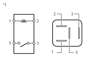
- INSPECT S-HORN RELAY
- Remove the S-HORN relay from the No. 1 engine room relay block and No. 1 junction block assembly.
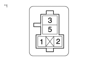
*1 S-HORN Relay - Measure the resistance according to the value(s) in the table below.
Standard Resistance
Tester Connection Condition Specified Condition 3 - 5 Auxiliary battery voltage not applied between terminals 1 and 2 10 kΩ or higher 3 - 5 Auxiliary battery voltage applied between terminals 1 and 2 Below 1 Ω Result
Proceed to OK NG
Result:
NG
REPLACE S-HORN RELAY
Result:
OK
See step 4
- Remove the S-HORN relay from the No. 1 engine room relay block and No. 1 junction block assembly.
- INSPECT POWER DISTRIBUTION BOX ASSEMBLY
- Remove the main body ECU (multiplex network body ECU).
Refer to REMOVAL [11/2023 - ]
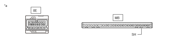
*a Component without harness connected
(Power Distribution Box Assembly)- - - Disconnect the 8E power distribution box assembly connector.
- Measure the resistance according to the value(s) in the table below.
Standard Resistance
Tester Connection Condition Specified Condition 8E-4 - MB-24 (SH) Always Below 1 Ω Result
Proceed to OK NG
Result:
NG
REPLACE POWER DISTRIBUTION BOX ASSEMBLY. Refer to REMOVAL [11/2023 - ]
Result:
OK
See step 5
- Remove the main body ECU (multiplex network body ECU).
- CHECK HARNESS AND CONNECTOR (AUXILIARY BATTERY - S-HORN RELAY)
- Measure the voltage according to the value(s) in the table below.
Standard Voltage
Tester Connection Condition Specified Condition S-HORN relay holder terminal 1 - Body ground Ignition switch off 11 to 14 V S-HORN relay holder terminal 5 - Body ground Ignition switch off 11 to 14 V *1 No. 1 Engine Room Relay Block and No. 1 Junction Block Assembly Result
Proceed to OK NG
Result:
NG
REPAIR OR REPLACE HARNESS OR CONNECTOR
Result:
OK
See step 6
- Measure the voltage according to the value(s) in the table below.
- CHECK HARNESS AND CONNECTOR (S-HORN RELAY - SECURITY HORN ASSEMBLY)
- Measure the resistance according to the value(s) in the table below.
Standard Resistance
Tester Connection Condition Specified Condition S-HORN relay holder terminal 3 - A20-1 Always Below 1 Ω S-HORN relay holder terminal 3 or A20-1 - Other terminals and body ground Always 10 kΩ or higher *1 No. 1 Engine Room Relay Block and No. 1 Junction Block Assembly Result
Proceed to OK NG
Result:
NG
REPAIR OR REPLACE HARNESS OR CONNECTOR
Result:
OK
See step 7
- Measure the resistance according to the value(s) in the table below.
- CHECK HARNESS AND CONNECTOR (S-HORN RELAY - POWER DISTRIBUTION BOX ASSEMBLY)
- Measure the resistance according to the value(s) in the table below.
Standard Resistance
Tester Connection Condition Specified Condition S-HORN relay holder terminal 2 - 8E-4 Always Below 1 Ω S-HORN relay holder terminal 2 or 8E-4 - Other terminals and body ground Always 10 kΩ or higher *1 No. 1 Engine Room Relay Block and No. 1 Junction Block Assembly Result
Proceed to OK NG
Result:
OK
REPLACE MAIN BODY ECU (MULTIPLEX NETWORK BODY ECU). Refer to REMOVAL [11/2023 - ]
Result:
NG
REPAIR OR REPLACE HARNESS OR CONNECTOR
- Measure the resistance according to the value(s) in the table below.