DTC C1AB3: Short to GND in Outer Mirror Indicator (Slave) [12/2019 - 11/2023]: Procedure
- CHECK DTC
- Turn the ignition switch off.
- Turn the ignition switch to ON.
- Recheck for DTCs and check if the same DTC is output again.
Body Electrical > Blind Spot Monitor Slave > Trouble Codes
OK
No DTCs are output.
Result
Result Proceed to OK A NG (w/ Seat Position Memory System) B NG (w/o Seat Position Memory System) C
Result:
A
USE SIMULATION METHOD TO CHECK. Refer to HOW TO PROCEED WITH TROUBLESHOOTING [12/2019 - ]
Result:
C
See step 6
Result:
B
See step 2
- CHECK HARNESS AND CONNECTOR (BLIND SPOT MONITOR SENSOR RH (SLAVE) - OUTER MIRROR CONTROL ECU ASSEMBLY RH)
- Disconnect the M2 blind spot monitor sensor RH (slave) connector.
- Disconnect the J7 outer mirror control ECU assembly RH connector.
- Measure the resistance according to the value(s) in the table below.
Standard Resistance
Tester Connection Condition Specified Condition M2-4 (OMIR) - Body ground Always 10 kΩ or higher Result
Proceed to OK NG
Result:
NG
REPAIR OR REPLACE HARNESS OR CONNECTOR
Result:
OK
See step 3
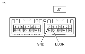
- INSPECT OUTER MIRROR CONTROL ECU ASSEMBLY RH
- Measure the resistance according to the value(s) in the table below.
*a Component without harness connected
(Outer Mirror Control ECU Assembly RH)Standard Resistance
Tester Connection Condition Specified Condition J7-13 (BDSR) - J7-7 (GND) Always 10 kΩ or higher Result
Proceed to OK NG
Result:
NG
REPLACE OUTER MIRROR CONTROL ECU ASSEMBLY RH. Refer to REMOVAL [12/2019 - ]
Result:
OK
See step 4
- Measure the resistance according to the value(s) in the table below.
- INSPECT OUTER MIRROR RH
- Remove the outer mirror RH.
Refer to REMOVAL [12/2019 - ]
- Inspect the outer rear view mirror indicator RH on the outer mirror RH.
Refer to INSPECTION [12/2019 - ]
Result
Proceed to OK NG
Result:
NG
REPLACE OUTER MIRROR RH. Refer to REMOVAL [12/2019 - ]
Result:
OK
See step 5
- Remove the outer mirror RH.
- INSPECT OUTER REAR VIEW MIRROR ASSEMBLY RH
- Remove the outer rear view mirror assembly RH.
Refer to REMOVAL [12/2019 - 11/2023]
- Inspect the outer rear view mirror assembly RH.
Refer to INSPECTION [12/2019 - ]
Result
Proceed to OK NG
Result:
OK
REPLACE BLIND SPOT MONITOR SENSOR RH (SLAVE). Refer to REMOVAL [12/2019 - 10/2022] , or refer to REMOVAL [10/2022 - 11/2023]
Result:
NG
REPLACE OUTER REAR VIEW MIRROR ASSEMBLY RH. Refer to REMOVAL [12/2019 - 11/2023]
- Remove the outer rear view mirror assembly RH.
- CHECK HARNESS AND CONNECTOR (BLIND SPOT MONITOR ASSEMBLY RH (SLAVE) - OUTER REAR VIEW MIRROR ASSEMBLY RH)
- Disconnect the M2 blind spot monitor sensor RH (slave) connector.
- Disconnect the J15 outer rear view mirror assembly RH connector.
- Measure the resistance according to the value(s) in the table below.
Standard Resistance
Tester Connection Condition Specified Condition M2-4 (OMIR) - Body ground Always 10 kΩ or higher Result
Proceed to OK NG
Result:
NG
REPAIR OR REPLACE HARNESS OR CONNECTOR
Result:
OK
See step 7
- INSPECT OUTER MIRROR RH
- Remove the outer mirror RH.
Refer to REMOVAL [12/2019 - ]
- Inspect the outer rear view mirror indicator RH on the outer mirror RH.
Refer to INSPECTION [12/2019 - ]
Result
Proceed to OK NG
Result:
NG
REPLACE OUTER MIRROR RH. Refer to REMOVAL [12/2019 - ]
Result:
OK
See step 8
- Remove the outer mirror RH.
- INSPECT OUTER REAR VIEW MIRROR ASSEMBLY RH
- Remove the outer rear view mirror assembly RH.
Refer to REMOVAL [12/2019 - 11/2023]
- Inspect the outer rear view mirror assembly RH.
Refer to INSPECTION [12/2019 - ]
Result
Proceed to OK NG
Result:
OK
REPLACE BLIND SPOT MONITOR SENSOR RH (SLAVE). Refer to REMOVAL [12/2019 - 10/2022] , or refer to REMOVAL [10/2022 - 11/2023]
Result:
NG
REPLACE OUTER REAR VIEW MIRROR ASSEMBLY RH. Refer to REMOVAL [12/2019 - 11/2023]
- Remove the outer rear view mirror assembly RH.