Terminals Of Ecu [12/2019 - ]
- CHECK MILLIMETER WAVE RADAR SENSOR ASSEMBLY NOTE:
- DTCs may be output when connectors are disconnected during inspection. Therefore, be sure to clear the DTCs using the GTS once the inspection has been completed.
- Do not apply excessive force to the forward recognition camera connector.
- Measure the voltage and resistance according to the value(s) in the table below.
Terminal No. (Symbol) Terminal Description Condition Specified Condition B6-1 (SGND) - Body ground Ground Always Below 1 Ω B6-8 (IGB) - B6-1 (SGND) Power source Ignition switch ON 10.5 to 16 V*1
11 to 14 V*2Ignition switch off Below 1 V - *1: w/ Stop and Start System
- *2: w/o Stop and Start System
- Check for pulses according to the value(s) in the table below.
HINT:
If the waveform is not similar to that shown in the illustration, a malfunction of a CAN bus line, terminating resistor, or the millimeter wave radar sensor assembly is suspected.
Terminal No. (Symbol) Terminal Description Condition Specified Condition B6-2 (CA2L) - B6-1 (SGND) CAN communication signal Ignition switch ON Pulse generation
(See waveform 2)B6-3 (CA2H) - B6-1 (SGND) CAN communication signal Ignition switch ON Pulse generation
(See waveform 1)B6-5 (CA1P) - B6-1 (SGND) CAN communication signal Ignition switch ON Pulse generation
(See waveform 1)B6-6 (CA1N) - B6-1 (SGND) CAN communication signal Ignition switch ON Pulse generation
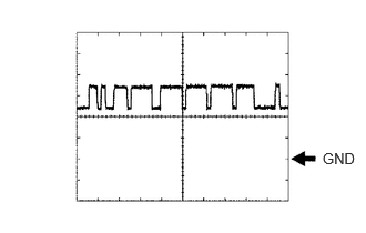
(See waveform 2)- Waveform 1
Item Content Tester Connection - Between B6-3 (CA2H) and B6-1 (SGND)
- Between B6-5 (CA1P) and B6-1 (SGND)
Tool Setting 1 V/DIV., 10 μs./DIV. Condition Ignition switch ON HINT:
The waveform varies depending on the CAN communication signal.
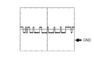
- Waveform 2
Item Content Tester Connection - Between B6-2 (CA2L) and B6-1 (SGND)
- Between B6-6 (CA1N) and B6-1 (SGND)
Tool Setting 1 V/DIV., 10 μs./DIV. Condition Ignition switch ON HINT:
The waveform varies depending on the CAN communication signal.
- Waveform 1