Clearance Warning ECU Power Source Circuit [12/2019 - 11/2023]: Procedure
- CHECK HARNESS AND CONNECTOR (CLEARANCE WARNING ECU ASSEMBLY POWER SOURCE)
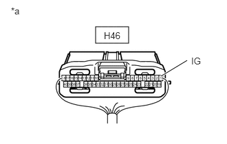
- Disconnect the H46 clearance warning ECU assembly connector.
*a Component with harness connector
(to Clearance Warning ECU Assembly) - Measure the voltage according to the value(s) in the table below.
Standard Voltage
Tester Connection Switch Condition Specified Condition H46-1 (IG) - Body ground Ignition switch ON 11 to 14 V*1
10.5 to 16 V*2H46-1 (IG) - Body ground Ignition switch off Below 1 V - *1: w/o Stop and Start System
- *2: w/ Stop and Start System
Result
Result Proceed to OK A NG (w/o Stop and Start System) B NG (w/ Stop and Start System) C
Result:
B
REPAIR OR REPLACE HARNESS OR CONNECTOR
Result:
C
GO TO STOP AND START SYSTEM. Refer to HOW TO PROCEED WITH TROUBLESHOOTING [12/2019 - 10/2022] , or refer to HOW TO PROCEED WITH TROUBLESHOOTING [10/2022 - ]
Result:
A
See step 2
- Disconnect the H46 clearance warning ECU assembly connector.
- CHECK HARNESS AND CONNECTOR (CLEARANCE WARNING ECU ASSEMBLY - BODY GROUND)
- Measure the resistance according to the value(s) in the table below.
Standard Resistance
Tester Connection Condition Specified Condition H46-28 (E) - Body ground Always Below 1 Ω Result
Proceed to OK NG
Result:
OK
PROCEED TO NEXT SUSPECTED AREA SHOWN IN PROBLEM SYMPTOMS TABLE. Refer to PROBLEM SYMPTOMS TABLE [12/2019 - 10/2022] , or refer to PROBLEM SYMPTOMS TABLE [10/2022 - 11/2023]
Result:
NG
REPAIR OR REPLACE HARNESS OR CONNECTOR
- Measure the resistance according to the value(s) in the table below.