Installation [12/2019 - ]: Procedure
WARNING: This page is about a different variant/trim than selected.
- INSTALL REAR ENGINE OIL SEAL
- Using height adjustment attachments and plate lift attachments, place the engine assembly on a flat level surface.NOTE:
- Using height adjustment attachments and plate lift attachments, keep the engine assembly level.
- To prevent the No. 2 oil pan sub-assembly from deforming, do not place any attachments under the No. 2 oil pan sub-assembly of the engine assembly.
- Using an engine sling device and engine lift, secure the engine assembly before servicing.
- Apply MP grease to the lip of a new rear engine oil seal.NOTE:
- Keep the lip free from foreign matter.
- Do not allow MP grease to contact the dust seal.
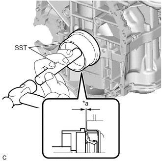
- Using SST and a hammer, tap in the rear engine oil seal.
*a -0.9 to 1.1 mm - SST: 09223-15030
- SST: 09950-70010
- 09951-07150
Standard Depth
-0.9 to 1.1 mm (-0.0354 to 0.0433 in.) (From the edge of the cylinder block sub-assembly and stiffening crankcase assembly)
NOTE:Do not tap in the rear engine oil seal at an angle.
- Using height adjustment attachments and plate lift attachments, place the engine assembly on a flat level surface.
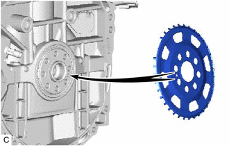
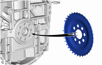
- INSTALL NO. 1 CRANKSHAFT POSITION SENSOR PLATE
- Type A:
- Type B:
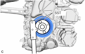
- INSTALL FLYWHEEL SUB-ASSEMBLY
- Using SST, hold the crankshaft pulley assembly.
- SST: 09213-54015
- SST: 09330-00021
- Clean the bolt holes.
- Apply adhesive to 2 or 3 threads at the end of each of the 8 new bolts.
Adhesive
Toyota Genuine Adhesive 1324, Three Bond 1324 or equivalent
- Install the flywheel sub-assembly with the 8 bolts. Uniformly tighten the 8 bolts in the sequence shown in the illustration.
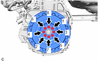 Courtesy of © TOYOTA, LICENSE AGREEMENT TMS1002
Torque: 150 N*m (1530 kgf*cm, 111 ft.*lbf)
NOTE:Do not start the engine for at least 1 hour after installing the flywheel sub-assembly.
- Using SST, hold the crankshaft pulley assembly.
- INSTALL TRANSMISSION INPUT DAMPER ASSEMBLY
- Using SST, hold the crankshaft pulley assembly.
- SST: 09213-54015
- SST: 09330-00021
- Install the transmission input damper assembly to the flywheel sub-assembly with 6 new bolts. Uniformly tighten the 6 bolts in the order shown in the illustration.
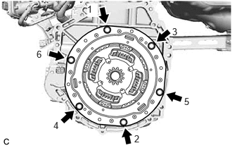 Courtesy of © TOYOTA, LICENSE AGREEMENT TMS1002
Torque: 30 N*m (306 kgf*cm, 22 ft.*lbf)
NOTE:- Make sure that there is no oil on the transmission input damper assembly and flywheel sub-assembly.
- Make sure to install the transmission input damper assembly in the correct direction.
- Do not allow grease to contact the splines of the transmission input damper assembly and the input shaft.
- Using SST, hold the crankshaft pulley assembly.
- INSTALL HYBRID VEHICLE TRANSAXLE ASSEMBLY
Refer to INSTALLATION [12/2019 - 11/2023] , or refer to INSTALLATION [11/2023 - ]