Terminals Of Ecu [12/2019 - ]
WARNING: This page is about a different variant/trim than selected.
- CHECK BRAKE BOOSTER WITH MASTER CYLINDER ASSEMBLY
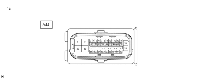
- Disconnect the A44 No. 1 skid control ECU (brake booster with master cylinder assembly) connector and measure the voltage or resistance on the wire harness side.
*a Front view of wire harness connector
(to No. 1 Skid Control ECU (Brake Booster with Master Cylinder Assembly))- - HINT:
The voltage cannot be measured with the connector connected to the No. 1 skid control ECU (brake booster with master cylinder assembly) as the connector is watertight.
STANDARDTerminal No. (Symbol) Terminal Description Condition Specified Condition A44-1 (MRI1) - Body ground Brake booster with accumulator pump assembly power supply input Always 11 to 14 V A44-2 (MGND) - Body ground Brake booster with accumulator pump assembly ground 1 minute or more after disconnecting the cable from the negative (-) auxiliary battery terminal Below 1 Ω A44-3 (SKS1) Brake pedal stroke sensor 1 signal input - - A44-4 - - - A44-5 - - - A44-6 - - - A44-7 - - - A44-8 - - - A44-9 - - - A44-10 - - - A44-11 - - - A44-12 (LBL) Brake fluid level warning switch (Brake master cylinder reservoir assembly) input - - A44-13 - - - A44-14 (+BI1) - Body ground +BI1 power source input Always 11 to 14 V A44-15 (BS) - Body ground Solenoid power supply input Always 11 to 14 V A44-16 (VSK1) Brake pedal stroke sensor 1 power supply output - - A44-17 - - - A44-18 (SKG1) Brake pedal stroke sensor 1 ground - - A44-19 - - - A44-20 - - - A44-21 - - - A44-22 - - - A44-23 - - - A44-24 - - - A44-25 (CSW2) No. 2 skid control ECU (brake actuator assembly) operation signal output - - A44-26 - - - A44-27 - - - A44-28 (GND1) - Body ground No. 1 skid control ECU (Brake booster with master cylinder assembly) ground 1 minute or more after disconnecting the cable from the negative (-) auxiliary battery terminal Below 1 Ω A44-29 (M+) Brake booster with accumulator pump assembly power supply (+) - - A44-30 (M-) Brake booster with accumulator pump assembly power supply (-) - - A44-31 (IG1) - Body ground IG1 power source input Ignition switch ON 11 to 14 V A44-32 - - - A44-33 - - - A44-34 - - - A44-35 (CA2H) CAN communication line 2 (H) - - A44-36 (CA2L) CAN communication line 2 (L) - - A44-37 (STP) - Body ground Stop light switch assembly input Stop light switch assembly on → off (Brake pedal depressed → released) 11 to 14 V → Below 1.5 V A44-38 (CA1H) CAN communication line 1 (H) - - A44-39 (CA1L) CAN communication line 1 (L) - - A44-40 (CTY) - Body ground Front door courtesy light switch assembly input (for driver side) Driver door closed → open 11 to 14 V or pulse output (maximum 14 V)* → Below 1 V A44-41 - - - A44-42 (IG2) - Body ground IG2 power source input Ignition switch ON 11 to 14 V *: Differs depending on the vehicle model
- Disconnect the A44 No. 1 skid control ECU (brake booster with master cylinder assembly) connector and measure the voltage or resistance on the wire harness side.
- CHECK BRAKE ACTUATOR ASSEMBLY
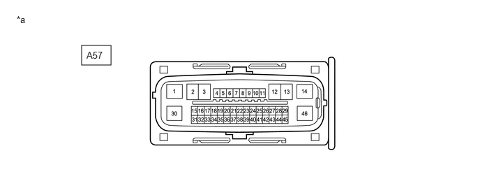
- Disconnect the A57 No. 2 skid control ECU (brake actuator assembly) connector and measure the voltage or resistance on the wire harness side.
*a Front view of wire harness connector
(to No. 2 Skid Control ECU (Brake Actuator Assembly))- - HINT:
The voltage cannot be measured with the connector connected to the No. 2 skid control ECU (brake actuator assembly) as the connector is watertight.
STANDARDTerminal No. (Symbol) Terminal Description Condition Specified Condition A57-1 (GND1) - Body ground No. 2 skid control ECU (brake actuator assembly) ground 1 minute or more after disconnecting the cable from the negative (-) auxiliary battery terminal Below 1 Ω A57-2 - - - A57-3 - - - A57-4 (RL-) Rear speed sensor LH (-) signal input - - A57-5 (RL+) Rear speed sensor LH (+) power supply output - - A57-6 (FR-) Front speed sensor RH (-) signal input - - A57-7 (FR+) Front speed sensor RH (+) power supply output - - A57-8 - - - A57-9 (CSW) - Body ground VSC OFF switch input VSC OFF switch is pushed → released Below 1 Ω → 10 kΩ or higher A57-10 (SKS2) Brake pedal stroke sensor 2 signal input - - A57-11 (STP) - Body ground Stop light switch assembly input Stop light switch assembly on → off (Brake pedal depressed → released) 11 to 14 V → Below 1.5 V A57-12 - - - A57-13 - - - A57-14 (+BS) - Body ground ABS solenoid relay power supply input Always 11 to 14 V A57-15 (IG2) - Body ground IG2 power source input Ignition switch ON 11 to 14 V A57-16 (CA2H) CAN communication line 2 (H) - - A57-17 (CA2L) CAN communication line 2 (L) - - A57-18 (SP1) Speed sensor signal output - - A57-19 (RR-) Rear speed sensor RH (-) signal input - - A57-20 (RR+) Rear speed sensor RH (+) power supply output - - A57-21 (FL-) Front speed sensor LH (-) signal input - - A57-22 (FL+) Front speed sensor LH (+) power supply output - - A57-23 - - - A57-24 - - - A57-25 (VSK2) Brake pedal stroke sensor 2 power supply output - - A57-26 (SKG2) Brake pedal stroke sensor 2 ground - - A57-27 (CANH) CAN communication line (H) - - A57-28 - - - A57-29 (CTY) - Body ground No. 2 Skid control ECU (brake actuator assembly) operation signal input Ignition switch ON 11 to 14 V A57-30 (GND2) - Body ground ABS motor ground 1 minute or more after disconnecting the cable from the negative (-) auxiliary battery terminal Below 1 Ω A57-31 - - - A57-32 (STPO) - Body ground Stop light control relay (Stop light switch assembly) output Always 11 to 14 V A57-33 - - - A57-34 - - - A57-35 (PKB) - Body ground Brake hold switch (Electric parking brake switch assembly) input Brake hold switch (electric parking brake switch assembly) is pushed → released Below 1 Ω → 10 kΩ or higher A57-36 - - - A57-37 (STP2) - Body ground Stop light control relay (Stop light switch assembly) input Stop light switch assembly on → off (Brake pedal depressed → released) 11 to 14 V → Below 1.5 V A57-38 - - - A57-39 - - - A57-40 - - - A57-41 - - - A57-42 - - - A57-43 (CANL) CAN communication line (L) - - A57-44 - - - A57-45 (IG1) - Body ground IG1 power source input Ignition switch ON 11 to 14 V A57-46 (BM) - Body ground ABS motor relay power supply input Always 11 to 14 V
- Disconnect the A57 No. 2 skid control ECU (brake actuator assembly) connector and measure the voltage or resistance on the wire harness side.