DTC P2530-14: Ignition Switch Run Position Circuit Short to Ground or Open [11/2023 - ]: Procedure
WARNING: This page is about a different variant/trim than selected.
- CHECK HARNESS AND CONNECTOR (IG2 TERMINAL)
- Make sure that there is no looseness at the locking part and the connecting part of the connector.
OK
The connector is securely connected.
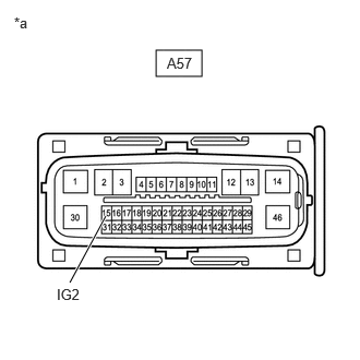
*a Front view of wire harness connector
(to No. 2 Skid Control ECU (Brake Actuator Assembly)) - Disconnect the A57 No. 2 skid control ECU (brake actuator assembly) connector.
- Check both the connector case and the terminals for deformation and corrosion.
OK
No deformation or corrosion.
- Turn the ignition switch to ON.
- Measure the voltage according to the value(s) in the table below.
Standard Voltage
Tester Connection Condition Specified Condition A57-15 (IG2) - Body ground Ignition switch ON 11 to 14 V Result
Proceed to OK NG
Result:
NG
REPAIR OR REPLACE HARNESS OR CONNECTOR
Result:
OK
See step 2
- Make sure that there is no looseness at the locking part and the connecting part of the connector.
- CHECK HARNESS AND CONNECTOR (GND1 TERMINAL)
- Measure the resistance according to the value(s) in the table below.
Standard Resistance
Tester Connection Condition Specified Condition A57-1 (GND1) - Body ground 1 minute or more after disconnecting the cable from the negative (-) auxiliary battery terminal Below 1 Ω Result
Proceed to OK NG
Result:
OK
REPLACE BRAKE ACTUATOR ASSEMBLY
Refer to REMOVAL [11/2023 - ]
Result:
NG
REPAIR OR REPLACE HARNESS OR CONNECTOR
- Measure the resistance according to the value(s) in the table below.