Abnormal Brake Pedal Response on First Depression [12/2019 - ]: Procedure
- BRAKE PROBLEM CHECK
- Check the conditions at the time the problem occurred.
- Whether a warning light illuminated or the buzzer sounded.
- The number of times the ignition switch was turned to ON since the latest symptom occurred.
- Frequency of the symptom.
Result
Proceed to NEXT
Result:
NEXT
See step 2
- Check the conditions at the time the problem occurred.
- CHECK DTC
- Check the DTCs (electronically controlled brake system) that are output.
Chassis > Brake Booster > Trouble Codes
Result
Result Proceed to DTCs C1256-00, C1256-09 and C1391-00 are not output. A DTCs C1256-00, C1256-09 and/or C1391-00 are output. B
Result:
B
REPAIR CIRCUITS INDICATED BY OUTPUT DTCS. Refer to DIAGNOSTIC TROUBLE CODE CHART [12/2019 - 10/2021] , or refer to DIAGNOSTIC TROUBLE CODE CHART [10/2021 - 11/2023] , or refer to DIAGNOSTIC TROUBLE CODE CHART [11/2023 - ]
Result:
A
See step 3
- Check the DTCs (electronically controlled brake system) that are output.
- CHECK VEHICLE
- Turn the ignition switch off.
- Depress the brake pedal within 4 minutes of opening the driver door and check the response of the brake pedal.
- Release the brake pedal and wait for 4 minutes without depressing the brake pedal, opening or closing the driver door or operating the ignition switch.
- After 4 minutes or more have elapsed, depress the brake pedal and check that the first depression response is different to successive depression responses.
HINT:
Compare the response of the brake pedal when the system is in sleep mode and when the stroke simulator is operating.
Result
Result Proceed to The response of the brake pedal does not change. A The response of the brake pedal changed. B
Result:
B
END
Result:
A
See step 4
- INSPECT FRONT DOOR COURTESY LIGHT SWITCH ASSEMBLY (FOR DRIVER SIDE)
- Set the interior light door switch to ON and check that the map light assembly illuminates, then set the interior light door switch to DOOR.
- Check that the map light assembly illuminates when the driver door is opened.
OK
The map light assembly illuminates when the driver door is opened.
Result
Proceed to OK NG
Result:
NG
INSPECT LIGHTING SYSTEM (COURTESY LIGHT SWITCH CIRCUIT). Refer to HOW TO PROCEED WITH TROUBLESHOOTING [12/2019 - 11/2023] , or refer to HOW TO PROCEED WITH TROUBLESHOOTING [11/2023 - ]
Result:
OK
See step 5
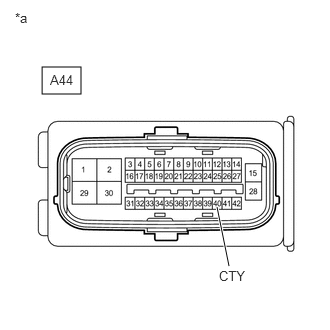
- CHECK HARNESS AND CONNECTOR (CTY TERMINAL)
- Make sure that there is no looseness at the locking part and the connecting part of the connector.
OK
The connector is securely connected.
*a Front view of wire harness connector
(to No. 1 Skid Control ECU (Brake Booster with Master Cylinder Assembly)) - Disconnect the A44 No. 1 skid control ECU (brake booster with master cylinder assembly) connector.
- Check both the connector case and the terminals for deformation and corrosion.
OK
No deformation or corrosion.
- Measure the voltage according to the value(s) in the table below.
Standard Voltage
Tester Connection Condition Specified Condition A44-40 (CTY) - Body ground Driver door open Below 1 V A44-40 (CTY) - Body ground Driver door closed 11 to 14 V or pulse output (maximum 14 V)* *: Differs depending on the vehicle model
Result
Proceed to OK NG
Result:
OK
REPLACE BRAKE BOOSTER WITH MASTER CYLINDER ASSEMBLY. Refer to REMOVAL [12/2019 - 10/2022] , or refer to REMOVAL [10/2022 - 11/2023] , or refer to REMOVAL [11/2023 - ]
Result:
NG
REPAIR OR REPLACE HARNESS OR CONNECTOR
- Make sure that there is no looseness at the locking part and the connecting part of the connector.