Terminals Of Ecu [11/2023 - ]
- CHECK MAIN BODY ECU (MULTIPLEX NETWORK BODY ECU) AND POWER DISTRIBUTION BOX ASSEMBLY Fig 1: Check Main Body ECU (Multiplex Network Body ECU) And Power Distribution Box Assembly [11/2023 - ]
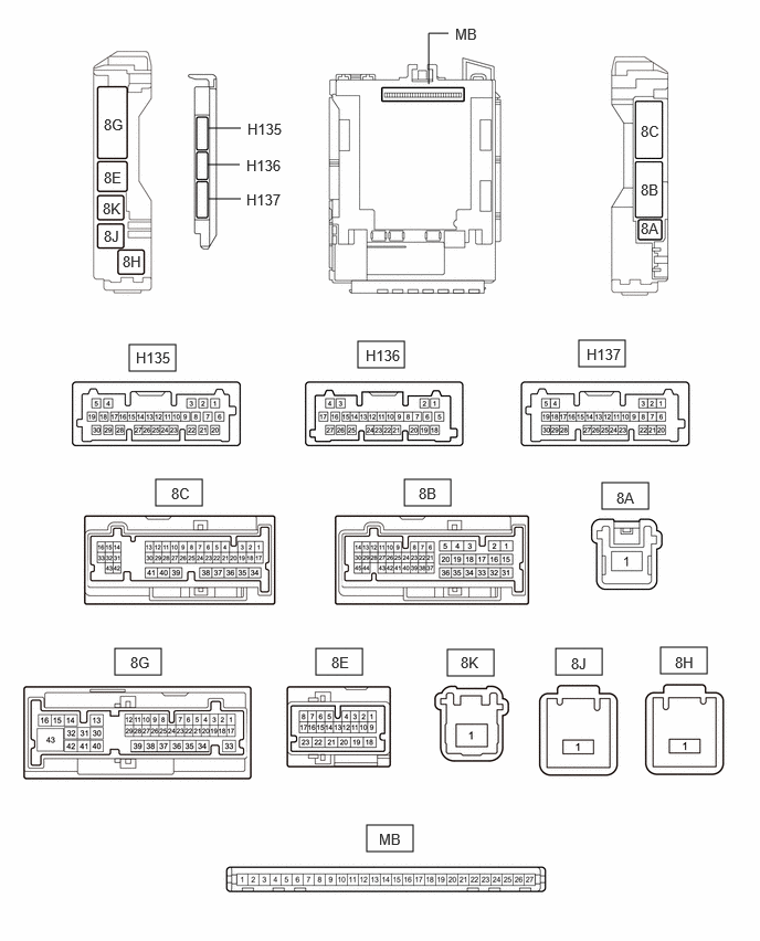 Courtesy of © TOYOTA, LICENSE AGREEMENT TMS1002
- Remove the main body ECU (multiplex network body ECU) from the power distribution box assembly.
Refer to REMOVAL [11/2023 - ]
- Reconnect the power distribution box assembly connectors.
- Measure the voltage and check for pulses according to the value(s) in the table below.
Terminal No. (Symbol) Terminal Description Condition Specified Condition MB-26 (BECU) - Body ground Auxiliary battery power supply Always 11 to 14 V MB-27 (IGR) - Body ground IG power supply Ignition switch off Below 1 V Ignition switch ON 11 to 14 V MB-22 (CXP1) - Body ground CXPI communication line Ignition switch off Below 1 V Ignition switch ON Pulse generation - Install the main body ECU (multiplex network body ECU) to the power distribution box assembly.
Refer to INSTALLATION [11/2023 - ]
- Connect the power distribution box assembly and main body ECU (multiplex network body ECU) connectors.
- Measure the voltage according to the value(s) in the table below.
Terminal No. (Symbol) Terminal Description Condition Specified Condition 8C-9 - Body ground Front door courtesy light switch RH input Front door RH open Below 1 V Front door RH closed 11 to 14 V or pulse output (maximum 14 V)*1 8G-3 - Body ground Front door courtesy light switch LH input Front door LH open Below 1 V Front door LH closed 11 to 14 V or pulse output (maximum 14 V)*1 8G-31 - Body ground Rear door courtesy light switch RH input Rear door RH open Below 1 V Rear door RH closed 11 to 14 V or pulse output (maximum 14 V)*1 8G-24 - Body ground Rear door courtesy light switch LH input Rear door LH open Below 1 V Rear door LH closed 11 to 14 V or pulse output (maximum 14 V)*1 8G-2 - Body ground Back door courtesy light switch input Back door open Below 1 V Back door closed 11 to 14 V or pulse output (maximum 14 V)*1 8C-4 - Body ground Each interior lights power supply DOME CUT relay off Below 1 V DOME CUT relay on 11 to 14 V 8G-20 - Body ground Each interior lights power supply DOME CUT relay off Below 1 V DOME CUT relay on 11 to 14 V 8G-22 - Body ground Instrument panel illumination power supply PANEL relay off Below 1 V PANEL relay on 11 to 14 V 8C-53 - Body ground Instrument panel illumination power supply PANEL relay off Below 1 V PANEL relay on 11 to 14 V 8C-18 - Body ground Ambient illumination lights ground*2 Ambient illumination light off 11 to 14 V Ambient illumination light on Below 1 V H135-3 (LSFR) - Body ground Front door unlock detection switch RH input Front door RH locked 11 to 14 V Front door RH unlocked Below 1 V H135-9 (LSFL) - Body ground Front door unlock detection switch LH input Front door LH locked 11 to 14 V Front door LH unlocked Below 1 V H136-23 (LSWR) - Body ground Rear door unlock detection switch RH input Rear door RH locked 11 to 14 V Rear door RH unlocked Below 1 V H135-10 (LSWL) - Body ground Rear door unlock detection switch LH input Rear door LH locked 11 to 14 V Rear door LH unlocked Below 1 V H135-5 (ILE) - Body ground Illuminated entry system drive output Illuminated entry system inactive 11 to 14 V Illuminated entry system operation Below 1 V H136-18 (FRCL) - Body ground Courtesy light assembly RH ground Courtesy light assembly RH off 11 to 14 V Courtesy light assembly RH on Below 1 V H136-19 (FLCL) - Body ground Courtesy light assembly LH ground Courtesy light assembly LH off 11 to 14 V Courtesy light assembly LH on Below 1 V *1: Differs depending on the vehicle model
*2: w/ Ambient Illumination Light
- Remove the main body ECU (multiplex network body ECU) from the power distribution box assembly.
- CHECK CERTIFICATION ECU (SMART KEY ECU ASSEMBLY)
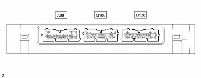 Courtesy of © TOYOTA, LICENSE AGREEMENT TMS1002
- Measure the voltage according to the value(s) in the table below.
Terminal No. (Symbol) Terminal Description Condition Specified Condition H138-20 (SWIL) - H138-30 (AGND) Push start switch illumination drive output Push start switch illumination on 11 to 14 V Push start switch illumination off Below 1 V
- Measure the voltage according to the value(s) in the table below.