IG Signal Circuit [12/2019 - 11/2023]: Procedure
- READ VALUE USING GTS
- Read the Data List according to the display on the GTS.
Body Electrical > Main Body > Data List
Tester Display Measurement Item Range Normal Condition Diagnostic Note IG SW Ignition switch ON signal OFF or ON OFF: Ignition switch off
ON: Ignition switch ON"OFF" is also displayed for this item when the ignition switch is ACC. Body Electrical > Main Body > Data List
Tester Display IG SW OK
Normal conditions listed above are displayed.
Result
Proceed to OK NG
Result:
OK
PROCEED TO NEXT SUSPECTED AREA SHOWN IN PROBLEM SYMPTOMS TABLE. Refer to PROBLEM SYMPTOMS TABLE [12/2019 - 11/2023]
Result:
NG
See step 2
- Read the Data List according to the display on the GTS.
- CHECK HARNESS AND CONNECTOR (POWER SOURCE CIRCUIT)
- Disconnect the 4F and 4B instrument panel junction block assembly connectors.
- Disconnect the H42 main body ECU (multiplex network body ECU) connector.
- Measure the voltage according to the value(s) in the table below.
Standard Voltage
Tester Connection Condition Specified Condition 4F-1 - Body ground Always*1
Ignition switch off*211 to 14 V *1: for Gasoline Model
*2: for HV Model
- Measure the resistance according to the value(s) in the table below.
Standard Resistance
Tester Connection Condition Specified Condition 4B-3 - Body ground Always Below 1 Ω H42-19 (GND2) - Body ground Always Below 1 Ω Result
Proceed to OK NG
Result:
NG
REPAIR OR REPLACE HARNESS OR CONNECTOR
Result:
OK
See step 3
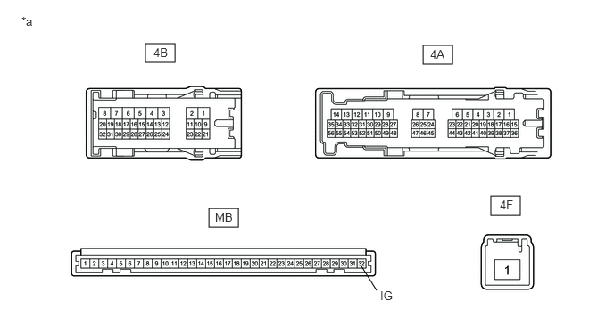
- INSPECT INSTRUMENT PANEL JUNCTION BLOCK ASSEMBLY
*a Component without harness connected (Instrument Panel Junction Block Assembly) - - - Remove the main body ECU (multiplex network body ECU) from the instrument panel junction block assembly.
Refer to REMOVAL [12/2019 - 10/2022] , or refer to REMOVAL [10/2022 - 11/2023]
- Measure the resistance according to the value(s) in the table below.
Standard Resistance
Tester Connection Condition Specified Condition 4F-1 - MB-32 (IG) Auxiliary battery not connected to 4A-17 and 4B-3 10 kΩ or higher 4F-1 - MB-32 (IG) Auxiliary battery positive (+) → 4A-17
Auxiliary battery negative (-) → 4B-3Below 1 Ω Result
Proceed to OK NG
Result:
OK
REPLACE MAIN BODY ECU (MULTIPLEX NETWORK BODY ECU). Refer to REMOVAL [12/2019 - 10/2022] , or refer to REMOVAL [10/2022 - 11/2023]
Result:
NG
REPLACE INSTRUMENT PANEL JUNCTION BLOCK ASSEMBLY. Refer to REMOVAL [12/2019 - 10/2022] , or refer to REMOVAL [10/2022 - 11/2023]
- Remove the main body ECU (multiplex network body ECU) from the instrument panel junction block assembly.