Interior Light Circuit [12/2019 - 11/2023]: Procedure
- PERFORM ACTIVE TEST USING GTS
- Perform the Active Test according to the display on the GTS.
Body Electrical > Main Body > Active Test
Tester Display Measurement Item Control Range Diagnostic Note Illuminated Entry System Turns on the lights that are controlled by the illuminated entry system* OFF or ON Perform the Active Test with the door linked switch of the map light assembly on, switches of the spot light assembly LH and RH off and switch of the No. 1 room light assembly in the DOOR position. - *: Refer to System Description for the lights that are controlled by the illuminated entry system.
Body Electrical > Main Body > Active Test
Tester Display Illuminated Entry System OK
All lights that are controlled by the illuminated entry system come on.
Result
Result Proceed to OK A NG (Map light assembly does not come on) B NG (Spot light assembly LH does not come on) C NG (Spot light assembly RH does not come on) D NG (No. 1 room light assembly does not come on) E NG (All lights that are controlled by the illuminated entry system do not come on) F
Result:
A
PROCEED TO NEXT SUSPECTED AREA SHOWN IN PROBLEM SYMPTOMS TABLE. Refer to PROBLEM SYMPTOMS TABLE [12/2019 - 11/2023]
Result:
C
GO TO PROBLEM SYMPTOMS TABLE (SPOT LIGHT ASSEMBLY LH). Refer to PROBLEM SYMPTOMS TABLE [12/2019 - 11/2023]
Result:
D
GO TO PROBLEM SYMPTOMS TABLE (SPOT LIGHT ASSEMBLY RH). Refer to PROBLEM SYMPTOMS TABLE [12/2019 - 11/2023]
Result:
E
GO TO PROBLEM SYMPTOMS TABLE (NO. 1 ROOM LIGHT ASSEMBLY). Refer to PROBLEM SYMPTOMS TABLE [12/2019 - 11/2023]
Result:
F
See step 4
Result:
B
See step 2
- Perform the Active Test according to the display on the GTS.
- INSPECT MAP LIGHT ASSEMBLY
Refer to INSPECTION [12/2019 - ]
Result
Proceed to OK NG Result:
NG
REPLACE MAP LIGHT ASSEMBLY. Refer to REMOVAL [12/2019 - ]
Result:
OK
See step 3
- CHECK HARNESS AND CONNECTOR (MAP LIGHT ASSEMBLY - INSTRUMENT PANEL JUNCTION BLOCK ASSEMBLY)
- Disconnect the 4B instrument panel junction block assembly connector.
- Measure the resistance according to the value(s) in the table below.
Standard Resistance
Tester Connection Condition Specified Condition R11-10 (+B1) - 4B-10 Always Below 1 Ω Result
Proceed to OK NG
Result:
OK
USE SIMULATION METHOD TO CHECK. Refer to HOW TO PROCEED WITH TROUBLESHOOTING [12/2019 - ]
Result:
NG
REPAIR OR REPLACE HARNESS OR CONNECTOR
- INSPECT MAP LIGHT ASSEMBLY
Refer to INSPECTION [12/2019 - ]
Result
Proceed to OK NG Result:
NG
REPLACE MAP LIGHT ASSEMBLY. Refer to REMOVAL [12/2019 - ]
Result:
OK
See step 5
- CHECK HARNESS AND CONNECTOR (MAP LIGHT ASSEMBLY - INSTRUMENT PANEL JUNCTION BLOCK ASSEMBLY)
- Disconnect the 4B instrument panel junction block assembly connector.
- Measure the resistance according to the value(s) in the table below.
Standard Resistance
Tester Connection Condition Specified Condition R11-10 (+B1) - 4B-10 Always Below 1 Ω R11-3 (DOOR) - 4B-29 Always Below 1 Ω R11-10 (+B1) or 4B-10 - Body ground Always 10 kΩ or higher R11-3 (DOOR) or 4B-29 - Body ground Always 10 kΩ or higher Result
Proceed to OK NG
Result:
NG
REPAIR OR REPLACE HARNESS OR CONNECTOR
Result:
OK
See step 6
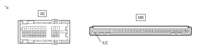
- INSPECT INSTRUMENT PANEL JUNCTION BLOCK ASSEMBLY
*a Component without harness connected
(Instrument Panel Junction Block Assembly)- - - Remove the main body ECU (multiplex network body ECU) from the instrument panel junction block assembly.
Refer to REMOVAL [12/2019 - 10/2022] , or refer to REMOVAL [10/2022 - 11/2023]
- Measure the resistance according to the value(s) in the table below.
Standard Resistance
Tester Connection Condition Specified Condition 4B-29 - MB-1 (ILE) Always Below 1 Ω Result
Proceed to OK NG
Result:
OK
REPLACE MAIN BODY ECU (MULTIPLEX NETWORK BODY ECU). Refer to REMOVAL [12/2019 - 10/2022] , or refer to REMOVAL [10/2022 - 11/2023]
Result:
NG
REPLACE INSTRUMENT PANEL JUNCTION BLOCK ASSEMBLY. Refer to REMOVAL [12/2019 - 10/2022] , or refer to REMOVAL [10/2022 - 11/2023]
- Remove the main body ECU (multiplex network body ECU) from the instrument panel junction block assembly.