DTC B1423: Open in Pressure Sensor Circuit / Abnormal Refrigerant Pressure [12/2019 - 10/2022]: Procedure
- CHECK FOR DTC
- Check for DTCs.
Body Electrical > Air Conditioner > Trouble Codes
Result
Result Proceed to DTC B1423 is output A DTC B1423 and B14B8 are output B
Result:
B
GO TO DTC B14B8. Refer to DTC B14B8: Refrigerant Shortage [12/2019 - 10/2022]
Result:
A
See step 2
- Check for DTCs.
- CHECK COMPARE REFRIGERANT GAS PRESSURE VALUES SHOWN ON GTS AND MANIFOLD GAUGE SET
- Install a manifold gauge set.
Refer to ON-VEHICLE INSPECTION [12/2019 - ]
- Prepare the vehicle according to the table below.MEASUREMENT CONDITION:
Item Condition Vehicle Condition Engine running Doors Fully closed (windows also fully closed) A/C Switch On Recirculation/fresh Control Switch Recirculation Set Temperature MAX COLD Blower Speed HI Air Conditioning Air Inlet Temperature 25 to 35°C (77 to 95°F) - Compare the values displayed in the Data List and on the manifold gauge.
Body Electrical > Air Conditioner > Data List
Tester Display Measurement Item Range Normal Condition Diagnostic Note Regulator Pressure Sensor Air conditioner pressure sensor Min.: -456.68 kPaG (gauge)
Max.: 3294.37 kPaG (gauge)Actual refrigerant pressure displayed - Refrigerant line (gas leak etc.)
- Air conditioner pressure sensor circuit malfunction
Body Electrical > Air Conditioner > Data List
Tester Display Regulator Pressure Sensor Result
Result Proceed to Data List value and manifold gauge set value do not match and Data List value: 196 kPa (2.0 kgf/cm2 ) or less A Data List value and manifold gauge set value do not match and Data List value: 2812 kPa (28.7 kgf/cm2 ) or less B Data List value matches manifold gauge set value C
Result:
B
See step 8
Result:
C
INSPECT REFRIGERANT PRESSURE WITH MANIFOLD GAUGE SET. Refer to ON-VEHICLE INSPECTION [12/2019 - ]
Result:
A
See step 3
- Install a manifold gauge set.
- READ VALUE USING GTS (REGULATOR PRESSURE SENSOR)
- Read the Data List according to the display on the GTS.
Body Electrical > Air Conditioner > Data List
Tester Display Measurement Item Range Normal Condition Diagnostic Note Regulator Pressure Sensor Air conditioner pressure sensor Min.: -456.68 kPaG (gauge)
Max.: 3294.37 kPaG (gauge)Actual refrigerant pressure displayed - Refrigerant line (gas leak etc.)
- Air conditioner pressure sensor circuit malfunction
Body Electrical > Air Conditioner > Data List
Tester Display Regulator Pressure Sensor OK
Disconnecting the connector of the air conditioner pressure sensor causes the Data List value to change.
Result
Result Proceed to Regulator pressure sensor value changes A Regulator pressure sensor value does not change B
Result:
B
See step 6
Result:
A
See step 4
- Read the Data List according to the display on the GTS.
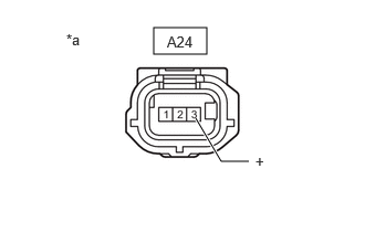
- CHECK HARNESS AND CONNECTOR (AIR CONDITIONER PRESSURE SENSOR - POWER SOURCE)
- Disconnect the A24 air conditioner pressure sensor connector.
*a Front view of wire harness connector
(to Air Conditioner Pressure Sensor) - Measure the voltage according to the value(s) in the table below.
Standard Voltage
Tester Connection Condition Specified Condition A24-3 (+) - Body ground Ignition switch ON 4.75 to 5.25 V Result
Proceed to OK NG
Result:
OK
REPLACE AIR CONDITIONER PRESSURE SENSOR. Refer to REMOVAL [12/2019 - 10/2022]
Result:
NG
See step 5
- Disconnect the A24 air conditioner pressure sensor connector.
- CHECK HARNESS AND CONNECTOR (AIR CONDITIONING AMPLIFIER ASSEMBLY - AIR CONDITIONER PRESSURE SENSOR)
- Disconnect the H63 air conditioning amplifier assembly connector.
- Disconnect the A24 air conditioner pressure sensor connector.
- Measure the resistance according to the value(s) in the table below.
Standard Resistance
Tester Connection Condition Specified Condition H63-11 (S5-3) - A24-3 (+) Always Below 1 Ω Result
Proceed to OK NG
Result:
OK
REPLACE AIR CONDITIONING AMPLIFIER ASSEMBLY. Refer to REMOVAL [12/2019 - 10/2022]
Result:
NG
REPAIR OR REPLACE HARNESS OR CONNECTOR
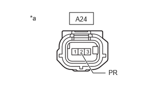
- CHECK HARNESS AND CONNECTOR (AIR CONDITIONER PRESSURE SENSOR - BODY GROUND)
- Disconnect the A24 air conditioner pressure sensor connector.
*a Front view of wire harness connector
(to Air Conditioner Pressure Sensor) - Measure the voltage according to the value(s) in the table below.
Standard Voltage
Tester Connection Condition Specified Condition A24-2 (PR) - Body ground Ignition switch ON 3.0 to 5.25 V Result
Proceed to OK NG
Result:
OK
REPLACE AIR CONDITIONING AMPLIFIER ASSEMBLY. Refer to REMOVAL [12/2019 - 10/2022]
Result:
NG
See step 7
- Disconnect the A24 air conditioner pressure sensor connector.
- CHECK HARNESS AND CONNECTOR (AIR CONDITIONING AMPLIFIER ASSEMBLY - AIR CONDITIONER PRESSURE SENSOR)
- Disconnect the H63 air conditioning amplifier assembly connector.
- Disconnect the A24 air conditioner pressure sensor connector.
- Measure the resistance according to the value(s) in the table below.
Standard Resistance
Tester Connection Condition Specified Condition H63-6 (PRE) or A24-2 (PR) - Other terminals and body ground Always 10 kΩ or higher Result
Proceed to OK NG
Result:
OK
REPLACE AIR CONDITIONING AMPLIFIER ASSEMBLY. Refer to REMOVAL [12/2019 - 10/2022]
Result:
NG
REPAIR OR REPLACE HARNESS OR CONNECTOR
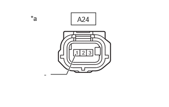
- CHECK HARNESS AND CONNECTOR (AIR CONDITIONER PRESSURE SENSOR - BODY GROUND)
- Disconnect the A24 air conditioner pressure sensor connector.
*a Front view of wire harness connector
(to Air Conditioner Pressure Sensor) - Measure the resistance according to the value(s) in the table below.
Standard Resistance
Tester Connection Condition Specified Condition A24-1 (-) - Body ground Always Below 1 Ω Result
Proceed to OK NG
Result:
NG
See step 14
Result:
OK
See step 9
- Disconnect the A24 air conditioner pressure sensor connector.
- CHECK HARNESS AND CONNECTOR (AIR CONDITIONER PRESSURE SENSOR - BODY GROUND)
- Disconnect the A24 air conditioner pressure sensor connector.
*a Front view of wire harness connector
(to Air Conditioner Pressure Sensor) - Measure the voltage according to the value(s) in the table below.
Standard Voltage
Tester Connection Condition Specified Condition A24-2 (PR) - Body ground Ignition switch ON 3.0 to 5.25 V Result
Result Proceed to 5.25 V or higher A 3.0 to 5.25 V B Below 3.0 V C
Result:
B
See step 11
Result:
C
See step 13
Result:
A
See step 10
- Disconnect the A24 air conditioner pressure sensor connector.
- CHECK HARNESS AND CONNECTOR (AIR CONDITIONING AMPLIFIER ASSEMBLY - AIR CONDITIONER PRESSURE SENSOR)
- Disconnect the H63 air conditioning amplifier assembly connector.
- Disconnect the A24 air conditioner pressure sensor connector.
- Measure the resistance according to the value(s) in the table below.
Standard Resistance
Tester Connection Condition Specified Condition H63-6 (PRE) or A24-2 (PR) - Other terminals and body ground Always 10 kΩ or higher Result
Proceed to OK NG
Result:
OK
REPLACE AIR CONDITIONING AMPLIFIER ASSEMBLY. Refer to REMOVAL [12/2019 - 10/2022]
Result:
NG
REPAIR OR REPLACE HARNESS OR CONNECTOR
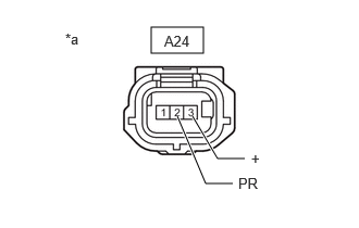
- CHECK AIR CONDITIONING AMPLIFIER ASSEMBLY (INTERNAL CIRCUIT RESISTANCE)
- Disconnect the A24 air conditioner pressure sensor connector.
*a Front view of wire harness connector
(to Air Conditioner Pressure Sensor) - Measure the resistance according to the value(s) in the table below.
Standard Resistance
Tester Connection Condition Specified Condition A24-2 (PR) - A24-3 (+) Ignition switch off 180 to 220 kΩ HINT:
After turning the ignition switch off, wait at least 30 seconds before performing the measurement.
Result
Proceed to OK NG
Result:
OK
REPLACE AIR CONDITIONER PRESSURE SENSOR. Refer to REMOVAL [12/2019 - 10/2022]
Result:
NG
See step 12
- Disconnect the A24 air conditioner pressure sensor connector.
- CHECK HARNESS AND CONNECTOR (AIR CONDITIONING AMPLIFIER ASSEMBLY - AIR CONDITIONER PRESSURE SENSOR)
- Disconnect the H63 air conditioning amplifier assembly connector.
- Disconnect the A24 air conditioner pressure sensor connector.
- Measure the resistance according to the value(s) in the table below.
Standard Resistance
Tester Connection Condition Specified Condition H63-6 (PRE) or A24-2 (PR) - Other terminals and body ground Always 10 kΩ or higher H63-11 (S5-3) or A24-3 (+) - Other terminals and body ground Always 10 kΩ or higher Result
Proceed to OK NG
Result:
OK
REPLACE AIR CONDITIONING AMPLIFIER ASSEMBLY. Refer to REMOVAL [12/2019 - 10/2022]
Result:
NG
REPAIR OR REPLACE HARNESS OR CONNECTOR
- CHECK HARNESS AND CONNECTOR (AIR CONDITIONING AMPLIFIER ASSEMBLY - AIR CONDITIONER PRESSURE SENSOR)
- Disconnect the H63 air conditioning amplifier assembly connector.
- Disconnect the A24 air conditioner pressure sensor connector.
- Measure the resistance according to the value(s) in the table below.
Standard Resistance
Tester Connection Condition Specified Condition H63-6 (PRE) - A24-2 (PR) Always Below 1 Ω Result
Proceed to OK NG
Result:
OK
REPLACE AIR CONDITIONING AMPLIFIER ASSEMBLY. Refer to REMOVAL [12/2019 - 10/2022]
Result:
NG
REPAIR OR REPLACE HARNESS OR CONNECTOR
- CHECK HARNESS AND CONNECTOR (AIR CONDITIONING AMPLIFIER ASSEMBLY - AIR CONDITIONER PRESSURE SENSOR)
- Disconnect the H63 air conditioning amplifier assembly connector.
- Disconnect the A24 air conditioner pressure sensor connector.
- Measure the resistance according to the value(s) in the table below.
Standard Resistance
Tester Connection Condition Specified Condition H63-15 (SG-4) - A24-1 (-) Always Below 1 Ω H63-15 (SG-4) or A24-1 (-) - Other terminals and body ground Always 10 kΩ or higher Result
Proceed to OK NG
Result:
OK
REPLACE AIR CONDITIONING AMPLIFIER ASSEMBLY. Refer to REMOVAL [12/2019 - 10/2022]
Result:
NG
REPAIR OR REPLACE HARNESS OR CONNECTOR