DTC B1497: Communication Malfunction (Bus Ic) [12/2019 - 10/2022]: Procedure
- PERFORM ACTIVE TEST USING GTS (SERVO PULSE)
- Perform the Active Test according to the display on the GTS.
Body Electrical > Air Conditioner > Active Test
Tester Display Measurement Item Control Range Diagnostic Note Air Mix Servo Targ Pulse(D) No. 1 air conditioning radiator damper servo sub-assembly (air mix) pulse Min.: 128
Max.: 383Operates between 165 to 257 pulses Air Inlet Damper Targ Pulse No. 1 blower damper servo sub-assembly pulse Min.: 128
Max.: 383Operates between 220 to 256 pulses Air Outlet Servo Pulse (P) No. 1 air conditioning radiator damper servo sub-assembly (mode) pulse Min.: 128
Max.: 383Operates between 234 to 348 pulses Body Electrical > Air Conditioner > Active Test
Tester Display Air Mix Servo Targ Pulse(D) Body Electrical > Air Conditioner > Active Test
Tester Display Air Inlet Damper Targ Pulse Body Electrical > Air Conditioner > Active Test
Tester Display Air Outlet Servo Pulse (P) OK
Damper servo motor is operated.
Result
Result Proceed to All damper servo motors are not operated A Any damper servo motor is not operated B All damper servo motors are operated C
Result:
B
REPLACE AIR CONDITIONING HARNESS ASSEMBLY. Refer to DISASSEMBLY [12/2019 - 10/2022]
Result:
C
REPLACE AIR CONDITIONING AMPLIFIER ASSEMBLY. Refer to REMOVAL [12/2019 - 10/2022]
Result:
A
See step 2
- Perform the Active Test according to the display on the GTS.
- CHECK AIR CONDITIONING AMPLIFIER ASSEMBLY
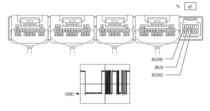
- Disconnect the q1 air conditioning amplifier assembly connector.
*a Component without harness connected
(Air Conditioning Amplifier Assembly)- - - Measure the resistance according to the value(s) in the table below.
Standard Resistance
Tester Connection Condition Specified Condition q1-2 (BUSG) - Body ground Always Below 1 Ω - Measure the voltage according to the value(s) in the table below.
Standard Voltage
Tester Connection Condition Specified Condition q1-4 (BUSB) - q1-2 (BUSG) Ignition switch off 11 to 14 V - Using an oscilloscope, check the waveform.
Item Content Tester Connection q1-3 (BUS) - q1-2 (BUSG) Tool Setting 2 V/DIV., 20 μs/DIV. Condition Ignition switch ON OK
The waveform displays properly.
Result
Proceed to OK NG
Result:
OK
REPLACE AIR CONDITIONING HARNESS ASSEMBLY. Refer to DISASSEMBLY [12/2019 - 10/2022]
Result:
NG
REPLACE AIR CONDITIONING AMPLIFIER ASSEMBLY. Refer to REMOVAL [12/2019 - 10/2022]
- Disconnect the q1 air conditioning amplifier assembly connector.