Blower Motor Circuit [12/2019 - 10/2022]: Procedure
- PERFORM ACTIVE TEST USING GTS (BLOWER MOTOR)
- Perform the Active Test according to the display on the GTS.
Body Electrical > Air Conditioner > Active Test
Tester Display Measurement Item Control Range Diagnostic Note Blower Motor Blower motor with fan sub-assembly Min.: 0
Max.: 31- Body Electrical > Air Conditioner > Active Test
Tester Display Blower Motor Result
Result Proceed to Blower motor with fan sub-assembly does not operate A Blower motor with fan sub-assembly operates but does not change speed B
Result:
B
See step 5
Result:
A
See step 2
- Perform the Active Test according to the display on the GTS.
- CHECK HARNESS AND CONNECTOR (BLOWER MOTOR WITH FAN SUB-ASSEMBLY - BATTERY AND BODY GROUND)
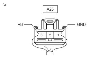
- Disconnect the A25 blower motor with fan sub-assembly connector.
*a Rear view of wire harness connector
(to Blower Motor with Fan Sub-assembly) - Measure the resistance according to the value(s) in the table below.
Standard Resistance
Tester Connection Condition Specified Condition A25-1 (GND) - Body ground Always Below 1 Ω - Measure the voltage according to the value(s) in the table below.
Standard Voltage
Tester Connection Condition Specified Condition A25-3 (+B) - Body ground Ignition switch off 11 to 14 V Result
Proceed to OK NG
Result:
NG
REPAIR OR REPLACE HARNESS OR CONNECTOR
Result:
OK
See step 3
- Disconnect the A25 blower motor with fan sub-assembly connector.
- CHECK HARNESS AND CONNECTOR (AIR CONDITIONING AMPLIFIER ASSEMBLY - BLOWER MOTOR WITH FAN SUB-ASSEMBLY)
- Disconnect the H62 air conditioning amplifier assembly connector.
- Disconnect the A25 blower motor with fan sub-assembly connector.
- Measure the resistance according to the value(s) in the table below.
Standard Resistance
Tester Connection Condition Specified Condition H62-21 (BLW) - A25-2 (SI) Always Below 1 Ω H62-21 (BLW) or A25-2 (SI) - Other terminals and body ground Always 10 kΩ or higher Result
Proceed to OK NG
Result:
NG
REPAIR OR REPLACE HARNESS OR CONNECTOR
Result:
OK
See step 4
- CHECK BLOWER MOTOR WITH FAN SUB-ASSEMBLY
- Connect the A25 blower motor with fan sub-assembly connector.
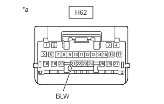
- Disconnect the H62 air conditioning amplifier assembly connector.
*a Front view of wire harness connector
(to Air Conditioning Amplifier Assembly) - Measure the voltage according to the value(s) in the table below.
Standard Voltage
Tester Connection Condition Specified Condition H62-21 (BLW) - Body ground Always 4.75 to 5.25 V Result
Proceed to OK NG
Result:
NG
REPLACE BLOWER MOTOR WITH FAN SUB-ASSEMBLY. Refer to REMOVAL [12/2019 - ]
Result:
OK
See step 5
- CHECK AIR CONDITIONING AMPLIFIER ASSEMBLY
- Connect the H62 air conditioning amplifier assembly connector.
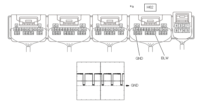
- Using an oscilloscope, check the waveform.
*a Component with harness connected
(Air Conditioning Amplifier Assembly)- - Item Content Terminal No. H62-21 (BLW) - H62-17 (GND) Tool Setting 2 V/DIV., 1 ms./DIV. Condition - Ignition switch ON
- Blower speed: LO
OK
Waveform is similar to that shown in the illustration.
HINT:
The waveform varies with the blower speed.
Result
Proceed to OK NG
Result:
OK
REPLACE BLOWER MOTOR WITH FAN SUB-ASSEMBLY. Refer to DISASSEMBLY [12/2019 - ]
Result:
NG
REPLACE AIR CONDITIONING AMPLIFIER ASSEMBLY. Refer to REMOVAL [12/2019 - 10/2022]