Inspection [12/2019 - ]: Procedure
- INSPECT NO. 1 COOLER THERMISTOR
- Measure the resistance according to the value(s) in the table below.
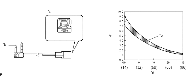
*a Component without harness connected
(No. 1 Cooler Thermistor)*b Sensing Portion *c Resistance (kΩ) *d Temperature (°C (°F)) *e Allowable Range - - Standard Resistance
Tester Connection Condition Specified Condition 1 - 2 -10°C (14°F) 7.30 to 9.10 kΩ -5°C (23°F) 5.65 to 6.95 kΩ 0°C (32°F) 4.40 to 5.35 kΩ 5°C (41°F) 3.40 to 4.15 kΩ 10°C (50°F) 2.70 to 3.25 kΩ 15°C (59°F) 2.14 to 2.58 kΩ 20°C (68°F) 1.71 to 2.05 kΩ 25°C (77°F) 1.38 to 1.64 kΩ 30°C (86°F) 1.11 to 1.32 kΩ NOTE:- Hold the sensor only by its connector. Touching the sensing portion may change the resistance value.
- When measuring, the sensor temperature must be the same as the ambient temperature.
HINT:
As the temperature increases, the resistance decreases (see the graph).
If the resistance is not as specified, replace the No. 1 cooler thermistor.
- Measure the resistance according to the value(s) in the table below.