Installation [12/2019 - ]: Procedure
- INSTALL NO. 1 COOLER THERMISTOR
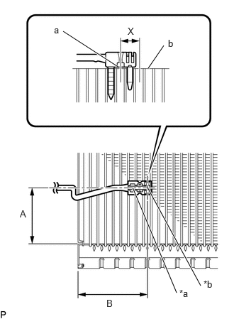
- w/o Stop And Start System:
- Install the No. 1 cooler thermistor as shown in the illustration.
*a Securing Part *b Sensor Part Installation Position
Part Length A 50.0 mm (1.97 in.) B 61.1 mm (2.41 in.) NOTE:- Be sure to insert the No. 1 cooler thermistor only once because reinserting it into the same position will not allow it to be firmly secured.
- When reusing the No. 1 cooler evaporator sub-assembly, insert the No. 1 cooler thermistor one row next to the one that has been used previously (X in the illustration).
- After inserting the No. 1 cooler thermistor, do not apply excessive force to the wire.
- Directly insert the No. 1 cooler thermistor until the edge of the plastic case "a" comes into contact with the No. 1 cooler evaporator sub-assembly "b".
- Install the No. 1 cooler thermistor as shown in the illustration.
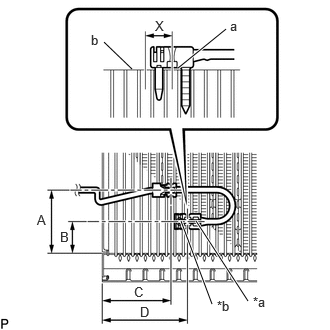
- w/ Stop And Start System:
- Install the No. 1 cooler thermistor as shown in the illustration.
*a Securing Part *b Sensor Part Installation Position
Part Length A 50.0 mm (1.97 in.) B 25.0 mm (0.984 in.) C 54.4 mm (2.14 in.) D 61.1 mm (2.41 in.) NOTE:- Be sure to insert the No. 1 cooler thermistor only once because reinserting it into the same position will not allow it to be firmly secured.
- When reusing the No. 1 cooler evaporator sub-assembly, insert the No. 1 cooler thermistor one row next to the one that has been used previously (X in the illustration).
- After inserting the No. 1 cooler thermistor, do not apply excessive force to the wire.
- Directly insert the No. 1 cooler thermistor until the edge of the plastic case "a" comes into contact with the No. 1 cooler evaporator sub-assembly "b".
- Install the No. 1 cooler thermistor as shown in the illustration.
- w/o Stop And Start System:
- INSTALL NO. 1 COOLER EVAPORATOR SUB-ASSEMBLY
Refer to PROCEDURE - Step 2 [12/2019 - 10/2022] , or refer to PROCEDURE - Step 2 [10/2022 - 11/2023] , or refer to PROCEDURE - Step 2 [11/2023 - ]
- INSTALL COOLER EXPANSION VALVE
Refer to PROCEDURE - Step 3 [12/2019 - 10/2022] , or refer to PROCEDURE - Step 3 [10/2022 - 11/2023] , or refer to PROCEDURE - Step 3 [11/2023 - ]
- INSTALL COOLING UNIT PARTS
Refer to PROCEDURE - Step 4 [12/2019 - 10/2022] , or refer to PROCEDURE - Step 4 [10/2022 - ]
- INSTALL HEATER RADIATOR UNIT SUB-ASSEMBLY
Refer to PROCEDURE - Step 5 [12/2019 - 10/2022] , or refer to PROCEDURE - Step 5 [10/2022 - ]
- INSTALL HEATER CLAMP
Refer to PROCEDURE - Step 6 [12/2019 - 10/2022] , or refer to PROCEDURE - Step 6 [10/2022 - ]
- INSTALL HEATER GROMMET
Refer to PROCEDURE - Step 7 [12/2019 - 10/2022] , or refer to PROCEDURE - Step 7 [10/2022 - ]
- INSTALL NO. 1 AIR CONDITIONING RADIATOR DAMPER SERVO SUB-ASSEMBLY
Refer to PROCEDURE - Step 9 [12/2019 - 10/2022] , or refer to PROCEDURE - Step 9 [10/2022 - 11/2023] , or refer to PROCEDURE - Step 9 [11/2023 - ]
- INSTALL AIR CONDITIONING HARNESS ASSEMBLY
Refer to PROCEDURE - Step 14 [12/2019 - 10/2022] , or refer to PROCEDURE - Step 14 [10/2022 - 11/2023] , or refer to PROCEDURE - Step 12 [11/2023 - ]
- INSTALL BLOWER ASSEMBLY
Refer to INSTALLATION [12/2019 - ]