DTC B1825: Short in Side Squib (LH) Circuit; DTC B1826: Open in Side Squib (LH) Circuit; DTC B1827: Short in Side Squib (LH) Circuit (to Ground); DTC B1828: Short in Side Squib (LH) Circuit (to +B) [12/2019 - 11/2023]: Procedure
- CHECK CONNECTORS
- Turn the ignition switch off.
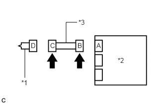
*1 Front Seat Airbag Assembly LH *2 Airbag Sensor Assembly *3 No. 2 Floor Wire - Disconnect the cable from the negative (-) auxiliary battery terminal.WARNING:
Wait at least 90 seconds after disconnecting the cable from the negative (-) auxiliary battery terminal to disable the SRS system.
- Check that the connectors are properly connected to the front seat airbag assembly LH and airbag sensor assembly.
OK
The connectors are properly connected.
HINT:
If the connectors are not properly connected, reconnect the connectors and proceed to the next inspection.
- Disconnect the connectors from the front seat airbag assembly LH and airbag sensor assembly.
- Check that the terminals of the connectors are not deformed or damaged.
OK
The terminals are not deformed or damaged.
- Check that the short springs of the activation prevention mechanism of the No. 2 floor wire connector are not deformed or damaged.
OK
The short springs are not deformed or damaged.
Result
Proceed to OK NG
Result:
NG
REPLACE NO. 2 FLOOR WIRE
Result:
OK
See step 2
- Turn the ignition switch off.
- CHECK FRONT SEAT AIRBAG ASSEMBLY LH
- Connect the connector to the airbag sensor assembly.
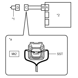
*1 Front Seat Airbag Assembly LH *2 Airbag Sensor Assembly *a Front view of wire harness connector
(to Front Seat Airbag Assembly LH) - Connect SST (resistance 2.1 Ω) to connector C.WARNING:
Never connect a tester to the front seat airbag assembly LH for measurement, as this may lead to a serious injury due to airbag deployment.
NOTE:- Do not forcibly insert SST into the terminals of the connector when connecting it.
- Insert SST straight into the terminals of the connector.
- SST: 09843-18061
- Connect the cable to the negative (-) auxiliary battery terminal.
- Turn the ignition switch to ON, and wait for at least 60 seconds.
- Clear the DTCs stored in memory.
Body Electrical > SRS Airbag > Clear DTCs
- Turn the ignition switch off.
- Turn the ignition switch to ON, and wait for at least 60 seconds.
- Check for DTCs.
Body Electrical > SRS Airbag > Trouble Codes
OK
DTC B1825, B1826, B1827 or B1828 is not output.
HINT:
Codes other than DTCs B1825, B1826, B1827 and B1828 may be output at this time, but they are not related to this check.
- Turn the ignition switch off.
- Disconnect the cable from the negative (-) auxiliary battery terminal.WARNING:
Wait at least 90 seconds after disconnecting the cable from the negative (-) auxiliary battery terminal to disable the SRS system.
- Disconnect SST from connector C.
Result
Proceed to OK NG
Result:
OK
REPLACE FRONT SEAT AIRBAG ASSEMBLY LH. Refer to REMOVAL [12/2019 - 10/2021] , or refer to REMOVAL [10/2021 - 10/2022] , or refer to REMOVAL [10/2022 - 11/2023]
Result:
NG
See step 3
- Connect the connector to the airbag sensor assembly.
- CHECK NO. 2 FLOOR WIRE
- Disconnect the No. 2 floor wire from the airbag sensor assembly.
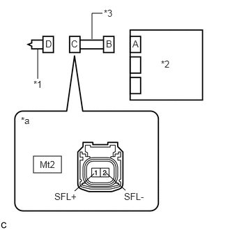
*1 Front Seat Airbag Assembly LH *2 Airbag Sensor Assembly *3 No. 2 Floor Wire *a Front view of wire harness connector
(to Front Seat Airbag Assembly LH) - Check for a short to B+ in the circuit.
- Connect the cable to the negative (-) auxiliary battery terminal.
- Turn the ignition switch to ON.
- Measure the voltage according to the value(s) in the table below.
Standard Voltage
Tester Connection Condition Specified Condition Mt2-1 (SFL+) - Body ground Ignition switch ON Below 1 V Mt2-2 (SFL-) - Body ground Ignition switch ON Below 1 V - Turn the ignition switch off.
- Disconnect the cable from the negative (-) auxiliary battery terminal.WARNING:
Wait at least 90 seconds after disconnecting the cable from the negative (-) auxiliary battery terminal to disable the SRS system.
- Check for an open in the circuit.
- Check for a short to ground in the circuit.
- Check for a short in the circuit.
- Release the activation prevention mechanism built into connector B.
Refer to SYSTEM DESCRIPTION [12/2019 - 10/2021] , or refer to SYSTEM DESCRIPTION [10/2021 - 11/2023]
- Measure the resistance according to the value(s) in the table below.
Standard Resistance
Tester Connection Condition Specified Condition Mt2-1 (SFL+) - Mt2-2 (SFL-) Always 1 MΩ or higher - Restore the released activation prevention mechanism of connector B to the original condition.
Result
Proceed to OK NG - Release the activation prevention mechanism built into connector B.
Result:
NG
REPLACE NO. 2 FLOOR WIRE
Result:
OK
See step 4
- Disconnect the No. 2 floor wire from the airbag sensor assembly.
- CHECK DTC
- Connect the connectors to the front seat airbag assembly LH and airbag sensor assembly.
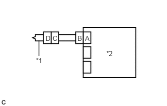
*1 Front Seat Airbag Assembly LH *2 Airbag Sensor Assembly - Connect the cable to the negative (-) auxiliary battery terminal.
- Turn the ignition switch to ON, and wait for at least 60 seconds.
- Clear the DTCs stored in memory.
Body Electrical > SRS Airbag > Clear DTCs
- Turn the ignition switch off.
- Turn the ignition switch to ON, and wait for at least 60 seconds.
- Check for DTCs.
Body Electrical > SRS Airbag > Trouble Codes
OK
DTC B1825, B1826, B1827 or B1828 is not output.
HINT:
Codes other than DTCs B1825, B1826, B1827 and B1828 may be output at this time, but they are not related to this check.
Result
Proceed to OK NG
Result:
OK
USE SIMULATION METHOD TO CHECK. Refer to HOW TO PROCEED WITH TROUBLESHOOTING [12/2019 - ]
Result:
NG
REPLACE AIRBAG SENSOR ASSEMBLY. Refer to REMOVAL [12/2019 - 10/2022] , or refer to REMOVAL [10/2022 - 11/2023]
- Connect the connectors to the front seat airbag assembly LH and airbag sensor assembly.