SRS Warning Light Remains ON [12/2019 - 10/2022]: Procedure
- CHECK SRS WARNING LIGHT OPERATION
- Turn the ignition switch to ON and check the SRS warning light condition.
HINT:
The primary check is performed for approximately 6 seconds after the ignition switch is turned to ON.
Result
Result Proceed to After the primary check period, the SRS warning light remains on. A After the primary check period, the SRS warning light turns off and comes on again. B
Result:
B
See step 6
Result:
A
See step 2
- Turn the ignition switch to ON and check the SRS warning light condition.
- CHECK AUXILIARY BATTERY VOLTAGE
- for Gasoline Model:
- Measure the voltage of the auxiliary battery.
Standard Voltage
11 to 14 V
- Measure the voltage of the auxiliary battery.
- for HV Model:
- Measure the voltage of the auxiliary battery with the ignition switch off.
Standard Voltage
11 to 14 V
Result
Proceed to OK NG - Measure the voltage of the auxiliary battery with the ignition switch off.
Result:
NG
INSPECT CHARGING SYSTEM AND AUXILIARY BATTERY
for A25A-FXS: Refer to ON-VEHICLE INSPECTION [12/2019 - 11/2023]
for 2GR-FKS without Stop And Start System: Refer to ON-VEHICLE INSPECTION [12/2019 - 10/2022]
for 2GR-FKS with Stop And Start System: Refer to ON-VEHICLE INSPECTION [12/2019 - 10/2022]
Result:
OK
See step 3
- for Gasoline Model:
- CHECK CONNECTOR
- Turn the ignition switch off.
- Disconnect the cable from the negative (-) auxiliary battery terminal.WARNING:
Wait at least 90 seconds after disconnecting the cable from the negative (-) auxiliary battery terminal to disable the SRS system.
- Check that the connector is properly connected to the airbag sensor assembly.
OK
The connector is properly connected.
HINT:
If the connector is not properly connected, reconnect the connector and proceed to the next inspection.
- Disconnect the connector from the airbag sensor assembly.
- Check that the terminals of the connector are not deformed or damaged.
OK
The terminals are not deformed or damaged.
Result
Proceed to OK NG
Result:
NG
REPLACE WIRE HARNESS
Result:
OK
See step 4
- CHECK WIRE HARNESS (AIRBAG SENSOR ASSEMBLY - BODY GROUND)
- Connect the cable to the negative (-) auxiliary battery terminal.
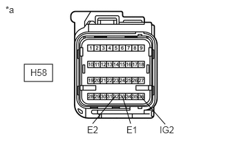
*a Front view of wire harness connector
(to Airbag Sensor Assembly) - Turn the ignition switch to ON.
- Operate all components of the electrical systems (defogger, wipers, headlights, heater blower, etc.).
- Measure the voltage according to the value(s) in the table below.
Standard Voltage
Tester Connection Condition Specified Condition H58-36 (IG2) - Body ground Ignition switch ON 8 to 16 V - Turn the ignition switch off.
- Measure the resistance according to the value(s) in the table below.
Standard Resistance
Tester Connection Condition Specified Condition H58-33 (E1) - Body ground Always Below 1 Ω H58-32 (E2) - Body ground Always Below 1 Ω Result
Proceed to OK NG
Result:
NG
REPLACE WIRE HARNESS
Result:
OK
See step 5
- Connect the cable to the negative (-) auxiliary battery terminal.
- CHECK SRS WARNING LIGHT
- Turn the ignition switch to ON and check the SRS warning light condition.
OK
After the primary check period, the SRS warning light turns off for approximately 10 seconds and then turns back on.
HINT:
The primary check period is approximately 6 seconds after the ignition switch is turned to ON.
Result
Proceed to OK NG
Result:
OK
REPLACE AIRBAG SENSOR ASSEMBLY. Refer to REMOVAL [12/2019 - 10/2022]
Result:
NG
REPLACE COMBINATION METER ASSEMBLY. Refer to REMOVAL [12/2019 - ]
- Turn the ignition switch to ON and check the SRS warning light condition.
- CHECK CAN COMMUNICATION SYSTEM
- Using the GTS, check if the CAN communication system is functioning normally.
OK
CAN communication system is functioning normally.
HINT:
Refer to Communication Bus Check in CAN Communication System.
for Gasoline Model: Refer to DIAGNOSIS SYSTEM [12/2019 - 09/2020] , or refer to DIAGNOSIS SYSTEM [09/2020 - 10/2022]
for HV Model: Refer to DIAGNOSIS SYSTEM [12/2019 - 09/2020] , or refer to DIAGNOSIS SYSTEM [09/2020 - 10/2021] , or refer to DIAGNOSIS SYSTEM [10/2021 - 10/2022]
Result
Proceed to OK NG
Result:
NG
GO TO CAN COMMUNICATION SYSTEM
for Gasoline Model: Refer to HOW TO PROCEED WITH TROUBLESHOOTING [12/2019 - 10/2022]
for HV Model: Refer to HOW TO PROCEED WITH TROUBLESHOOTING [12/2019 - 10/2021] , or refer to HOW TO PROCEED WITH TROUBLESHOOTING [10/2021 - 10/2022]
Result:
OK
See step 7
- Using the GTS, check if the CAN communication system is functioning normally.
- CHECK AUXILIARY BATTERY VOLTAGE
- for Gasoline Model:
- Measure the voltage of the auxiliary battery.
Standard Voltage
11 to 14 V
- Measure the voltage of the auxiliary battery.
- for HV Model:
- Measure the voltage of the auxiliary battery with the ignition switch off.
Standard Voltage
11 to 14 V
Result
Proceed to OK NG - Measure the voltage of the auxiliary battery with the ignition switch off.
Result:
NG
INSPECT CHARGING SYSTEM AND AUXILIARY BATTERY
for A25A-FXS: Refer to ON-VEHICLE INSPECTION [12/2019 - 11/2023]
for 2GR-FKS without Stop And Start System: Refer to ON-VEHICLE INSPECTION [12/2019 - 10/2022]
for 2GR-FKS with Stop And Start System: Refer to ON-VEHICLE INSPECTION [12/2019 - 10/2022]
Result:
OK
See step 8
- for Gasoline Model:
- CHECK CONNECTOR
- Turn the ignition switch off.
- Disconnect the cable from the negative (-) auxiliary battery terminal.WARNING:
Wait at least 90 seconds after disconnecting the cable from the negative (-) auxiliary battery terminal to disable the SRS system.
- Check that the connector is properly connected to the airbag sensor assembly.
OK
The connector is properly connected.
HINT:
If the connector is not properly connected, reconnect the connector and proceed to the next inspection.
- Disconnect the connector from the airbag sensor assembly.
- Check that the terminals of the connector are not deformed or damaged.
OK
The terminals are not deformed or damaged.
Result
Proceed to OK NG
Result:
NG
REPLACE WIRE HARNESS
Result:
OK
See step 9
- CHECK WIRE HARNESS (AIRBAG SENSOR ASSEMBLY - BODY GROUND)
- Connect the cable to the negative (-) auxiliary battery terminal.
*a Front view of wire harness connector
(to Airbag Sensor Assembly) - Turn the ignition switch to ON.
- Operate all components of the electrical systems (defogger, wipers, headlights, heater blower, etc.).
- Measure the voltage according to the value(s) in the table below.
Standard Voltage
Tester Connection Condition Specified Condition H58-36 (IG2) - Body ground Ignition switch ON 8 to 16 V - Turn the ignition switch off.
- Measure the resistance according to the value(s) in the table below.
Standard Resistance
Tester Connection Condition Specified Condition H58-33 (E1) - Body ground Always Below 1 Ω H58-32 (E2) - Body ground Always Below 1 Ω Result
Proceed to OK NG
Result:
NG
REPLACE WIRE HARNESS
Result:
OK
See step 10
- Connect the cable to the negative (-) auxiliary battery terminal.
- CHECK CONNECTOR
- Disconnect the cable from the negative (-) auxiliary battery terminal.WARNING:
Wait at least 90 seconds after disconnecting the cable from the negative (-) auxiliary battery terminal to disable the SRS system.
- Check that the connector is properly connected to the combination meter assembly.
OK
The connector is properly connected.
HINT:
If the connector is not properly connected, reconnect the connector and proceed to the next inspection.
- Disconnect the connector from the combination meter assembly.
- Check that the terminals of the connector are not deformed or damaged.
OK
The terminals are not deformed or damaged.
Result
Proceed to OK NG
Result:
NG
REPAIR OR REPLACE CONNECTOR
Result:
OK
See step 11
- Disconnect the cable from the negative (-) auxiliary battery terminal.
- CHECK WIRE HARNESS (COMBINATION METER ASSEMBLY - BODY GROUND)
- Connect the cable to the negative (-) auxiliary battery terminal.
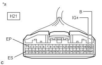
*a Front view of wire harness connector
(to Combination Meter Assembly) - Turn the ignition switch to ON.
- Measure the voltage according to the value(s) in the table below.
Standard Voltage (for Gasoline Model)
Tester Connection Condition Specified Condition H21-39 (IG+) - Body ground Ignition switch ON 11 to 14 V*1
10.5 to 16 V*2H21-40 (B) - Body ground Always 11 to 14 V *1: w/o Stop and Start System
*2: w/ Stop and Start System
Standard Voltage (for HV Model)
Tester Connection Condition Specified Condition H21-39 (IG+) - Body ground Ignition switch ON 11 to 14 V H21-40 (B) - Body ground Ignition switch off 11 to 14 V - Turn the ignition switch off.
- Measure the resistance according to the value(s) in the table below.
Standard Resistance
Tester Connection Condition Specified Condition H21-21 (ES) - Body ground Always Below 1 Ω H21-2 (EP) - Body ground Always Below 1 Ω Result
Proceed to OK NG
Result:
NG
REPAIR OR REPLACE WIRE HARNESS
Result:
OK
See step 12
- Connect the cable to the negative (-) auxiliary battery terminal.
- CHECK SRS WARNING LIGHT
- Disconnect the cable from the negative (-) auxiliary battery terminal.WARNING:
Wait at least 90 seconds after disconnecting the cable from the negative (-) auxiliary battery terminal to disable the SRS system.
- Connect the connector to the combination meter assembly.
- Connect the cable to the negative (-) auxiliary battery terminal.
- Turn the ignition switch to ON and check the SRS warning light condition.
OK
After the primary check period, the SRS warning light turns off for approximately 10 seconds and then turns back on.
HINT:
The primary check period is approximately 6 seconds after the ignition switch is turned to ON.
Result
Proceed to OK NG
Result:
OK
REPLACE AIRBAG SENSOR ASSEMBLY. Refer to REMOVAL [12/2019 - 10/2022]
Result:
NG
REPLACE COMBINATION METER ASSEMBLY. Refer to REMOVAL [12/2019 - ]
- Disconnect the cable from the negative (-) auxiliary battery terminal.