SRS Warning Light Remains ON [11/2023 - ]: Procedure
- CHECK SRS WARNING LIGHT OPERATION
- Turn the ignition switch to ON and check the SRS warning light condition.
HINT:
The primary check is performed for approximately 6 seconds after the ignition switch is turned to ON.
Result
Result Proceed to After the primary check period, the SRS warning light remains on. A After the primary check period, the SRS warning light goes off and comes on again. B
Result:
B
See step 7
Result:
A
See step 2
- Turn the ignition switch to ON and check the SRS warning light condition.
- CHECK AUXILIARY BATTERY
- Measure the auxiliary battery voltage with the ignition switch off.
Standard Voltage
11 to 14 V
Result
Proceed to OK NG
Result:
NG
REPLACE OR RECHARGE AUXILIARY BATTERY
Result:
OK
See step 3
- Measure the auxiliary battery voltage with the ignition switch off.
- CHECK CONNECTION OF CONNECTOR
- Turn the ignition switch off.
- Disconnect the cable from the negative (-) auxiliary battery terminal, and wait for at least 60 seconds.
- Check that the connector is properly connected to the airbag sensor assembly.
OK
The connector is properly connected.
Result
Proceed to OK NG
Result:
NG
CONNECT CONNECTOR PROPERLY
Result:
OK
See step 4
- CHECK CONNECTOR
- Disconnect the airbag sensor assembly connector.
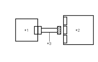
*1 Combination Meter Assembly *2 Airbag Sensor Assembly *3 Wire Harness - Check that the terminals of the connector are not deformed or damaged.
OK
The terminals are not deformed or damaged.
Result
Proceed to OK NG
Result:
NG
REPAIR OR REPLACE HARNESS OR CONNECTOR
Result:
OK
See step 5
- Disconnect the airbag sensor assembly connector.
- CHECK HARNESS AND CONNECTOR (AIRBAG SENSOR ASSEMBLY - AUXILIARY BATTERY AND BODY GROUND)
- Connect the cable to the negative (-) auxiliary battery terminal, and wait for at least 2 seconds.
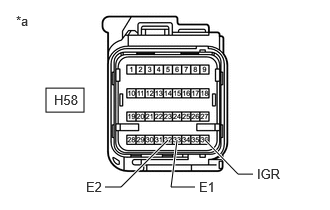
*a Front view of wire harness connector
(to Airbag Sensor Assembly) - Turn the ignition switch to ON.
- Operate all components of the electrical systems (defogger, wipers, headlights, heater blower, etc.).
- Measure the voltage according to the value(s) in the table below.
Standard Voltage
Tester Connection Condition Specified Condition H58-36 (IGR) - Body ground Ignition switch ON 8 to 16 V - Turn the ignition switch off.
- Measure the resistance according to the value(s) in the table below.
Standard Resistance
Tester Connection Condition Specified Condition H58-33 (E1) - Body ground Always Below 1 Ω H58-32 (E2) - Body ground Always Below 1 Ω Result
Proceed to OK NG
Result:
NG
REPAIR OR REPLACE HARNESS OR CONNECTOR
Result:
OK
See step 6
- Connect the cable to the negative (-) auxiliary battery terminal, and wait for at least 2 seconds.
- CHECK SRS WARNING LIGHT
- Turn the ignition switch to ON.
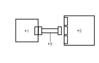
*1 Combination Meter Assembly *2 Airbag Sensor Assembly *3 Wire Harness - Approximately 6 seconds after the ignition switch is turned to ON, check the condition of the SRS warning light.
Result
Result Proceed to Turns off for 10 seconds, and then illuminates A Turns off for 10 seconds, and then remains off B
Result:
A
REPLACE AIRBAG SENSOR ASSEMBLY. Refer to REMOVAL [11/2023 - ]
Result:
B
REPLACE COMBINATION METER ASSEMBLY. Refer to REMOVAL [12/2019 - ]
- Turn the ignition switch to ON.
- CHECK CAN COMMUNICATION SYSTEM
- Check if a CAN communication DTC is output.
for HV Model: Refer to DIAGNOSIS SYSTEM [11/2023 - ]
for Gasoline Model: Refer to DIAGNOSIS SYSTEM [11/2023 - ]
Result
Result Proceed to DTC is not output A DTCs are output B
Result:
B
GO TO CAN COMMUNICATION SYSTEM
for HV Model: Refer to HOW TO PROCEED WITH TROUBLESHOOTING [11/2023 - ]
for Gasoline Model: Refer to HOW TO PROCEED WITH TROUBLESHOOTING [11/2023 - ]
Result:
A
See step 8
- Check if a CAN communication DTC is output.
- CHECK AUXILIARY BATTERY
- Measure the auxiliary battery voltage with the ignition switch off.
Standard Voltage
11 to 14 V
Result
Proceed to OK NG
Result:
NG
REPLACE OR RECHARGE AUXILIARY BATTERY
Result:
OK
See step 9
- Measure the auxiliary battery voltage with the ignition switch off.
- CHECK CONNECTION OF CONNECTORS
- Turn the ignition switch off.
- Disconnect the cable from the negative (-) auxiliary battery terminal, and wait for at least 60 seconds.
- Check that the connectors are properly connected to the airbag sensor assembly and combination meter assembly.
OK
The connectors are properly connected.
Result
Proceed to OK NG
Result:
NG
CONNECT CONNECTORS PROPERLY
Result:
OK
See step 10
- CHECK CONNECTORS
- Disconnect the airbag sensor assembly connector.
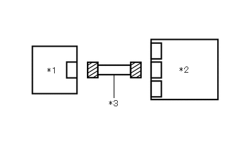
*1 Combination Meter Assembly *2 Airbag Sensor Assembly *3 Wire Harness - Disconnect the combination meter assembly connector.
- Check that the terminals of the connectors are not deformed or damaged.
OK
The terminals are not deformed or damaged.
Result
Proceed to OK NG
Result:
NG
REPAIR OR REPLACE HARNESS OR CONNECTOR
Result:
OK
See step 11
- Disconnect the airbag sensor assembly connector.
- CHECK HARNESS AND CONNECTOR (AIRBAG SENSOR ASSEMBLY - AUXILIARY BATTERY AND BODY GROUND)
- Connect the cable to the negative (-) auxiliary battery terminal, and wait for at least 2 seconds.
*a Front view of wire harness connector
(to Airbag Sensor Assembly) - Turn the ignition switch to ON.
- Operate all components of the electrical systems (defogger, wipers, headlights, heater blower, etc.).
- Measure the voltage according to the value(s) in the table below.
Standard Voltage
Tester Connection Condition Specified Condition H58-36 (IGR) - Body ground Ignition switch ON 8 to 16 V - Turn the ignition switch off.
- Measure the resistance according to the value(s) in the table below.
Standard Resistance
Tester Connection Condition Specified Condition H58-33 (E1) - Body ground Always Below 1 Ω H58-32 (E2) - Body ground Always Below 1 Ω Result
Proceed to OK NG
Result:
NG
REPAIR OR REPLACE HARNESS OR CONNECTOR
Result:
OK
See step 12
- Connect the cable to the negative (-) auxiliary battery terminal, and wait for at least 2 seconds.
- CHECK HARNESS AND CONNECTOR (COMBINATION METER ASSEMBLY - AUXILIARY BATTERY AND BODY GROUND)
- Turn the ignition switch to ON.
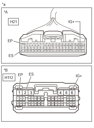
*A except 12.3 Inch Display *B for 12.3 Inch Display *a Front view of wire harness connector
(to Combination Meter Assembly) - Measure the voltage according to the value(s) in the table below.
Standard Voltage
EXCEPT 12.3 INCH DISPLAYTester Connection Condition Specified Condition H21-39 (IG+) - Body ground Ignition switch ON 11 to 14 V*1
10.5 to 16 V*2*1: w/o Stop and Start System
*2: w/ Stop and Start System
FOR 12.3 INCH DISPLAYTester Connection Condition Specified Condition H112-6 (IG+) - Body ground Ignition switch ON 11 to 14 V*1
10.5 to 16 V*2*1: w/o Stop and Start System
*2: w/ Stop and Start System
- Turn the ignition switch off.
- Measure the resistance according to the value(s) in the table below.
Standard Resistance
EXCEPT 12.3 INCH DISPLAYTester Connection Condition Specified Condition H21-2 (EP) - Body ground Always Below 1 Ω H21-21 (ES) - Body ground Always Below 1 Ω FOR 12.3 INCH DISPLAYTester Connection Condition Specified Condition H112-1 (EP) - Body ground Always Below 1 Ω H112-2 (ES) - Body ground Always Below 1 Ω Result
Proceed to OK NG
Result:
NG
REPAIR OR REPLACE HARNESS OR CONNECTOR
Result:
OK
See step 13
- Turn the ignition switch to ON.
- CHECK SRS WARNING LIGHT
- Disconnect the cable from the negative (-) auxiliary battery terminal, and wait for at least 60 seconds.
*1 Combination Meter Assembly *2 Airbag Sensor Assembly *3 Wire Harness - Connect the combination meter assembly connector.
- Connect the cable to the negative (-) auxiliary battery terminal, and wait for at least 2 seconds.
- Turn the ignition switch to ON.
- Approximately 6 seconds after the ignition switch is turned to ON, check the condition of the SRS warning light.
Result
Result Proceed to Turns off for 10 seconds, and then illuminates A Turns off for 10 seconds, and then remains off B
Result:
A
REPLACE AIRBAG SENSOR ASSEMBLY. Refer to REMOVAL [11/2023 - ]
Result:
B
REPLACE COMBINATION METER ASSEMBLY. Refer to REMOVAL [12/2019 - ]
- Disconnect the cable from the negative (-) auxiliary battery terminal, and wait for at least 60 seconds.