SRS Warning Light does not Come ON [10/2022 - 11/2023]: Procedure
- CHECK AUXILIARY BATTERY VOLTAGE
- for Gasoline Model:
- Measure the voltage of the auxiliary battery.
Standard Voltage
11 to 14 V
- Measure the voltage of the auxiliary battery.
- for HV Model:
- Measure the voltage of the auxiliary battery with the ignition switch off.
Standard Voltage
11 to 14 V
Result
Proceed to OK NG - Measure the voltage of the auxiliary battery with the ignition switch off.
Result:
NG
INSPECT CHARGING SYSTEM AND AUXILIARY BATTERY
for A25A-FXS: Refer to ON-VEHICLE INSPECTION [12/2019 - 11/2023]
for T24A-FTS: Refer to ON-VEHICLE INSPECTION [10/2022 - ]
Result:
OK
See step 2
- for Gasoline Model:
- CHECK CONNECTOR
- Turn the ignition switch off.
- Disconnect the cable from the negative (-) auxiliary battery terminal.WARNING:
Wait at least 90 seconds after disconnecting the cable from the negative (-) auxiliary battery terminal to disable the SRS system.
- Check that the connector is properly connected to the combination meter assembly.
OK
The connector is properly connected.
HINT:
If the connector is not properly connected, reconnect the connector and proceed to the next inspection.
- Disconnect the connector from the combination meter assembly.
- Check that the terminals of the connector are not deformed or damaged.
OK
The terminals are not deformed or damaged.
Result
Proceed to OK NG
Result:
NG
REPAIR OR REPLACE CONNECTOR
Result:
OK
See step 3
- CHECK WIRE HARNESS (COMBINATION METER ASSEMBLY - BODY GROUND)
- Connect the cable to the negative (-) auxiliary battery terminal.
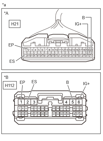
*A except 12.3 Inch Display *B for 12.3 Inch Display *a Front view of wire harness connector
(to Combination Meter Assembly) - Turn the ignition switch to ON.
- Measure the voltage according to the value(s) in the table below.
Standard Voltage (for Gasoline Model)
EXCEPT 12.3 INCH DISPLAYTester Connection Condition Specified Condition H21-39 (IG+) - Body ground Ignition switch ON 11 to 14 V*1
10.5 to 16 V*2H21-40 (B) - Body ground Always 11 to 14 V *1: w/o Stop and Start System
*2: w/ Stop and Start System
FOR 12.3 INCH DISPLAYTester Connection Condition Specified Condition H112-6 (IG+) - Body ground Ignition switch ON 11 to 14 V*1
10.5 to 16 V*2H112-5 (B) - Body ground Always 11 to 14 V *1: w/o Stop and Start System
*2: w/ Stop and Start System
Standard Voltage (for HV Model)
EXCEPT 12.3 INCH DISPLAYTester Connection Condition Specified Condition H21-39 (IG+) - Body ground Ignition switch ON 11 to 14 V H21-40 (B) - Body ground Ignition switch off 11 to 14 V FOR 12.3 INCH DISPLAYTester Connection Condition Specified Condition H112-6 (IG+) - Body ground Ignition switch ON 11 to 14 V H112-5 (B) - Body ground Ignition switch off 11 to 14 V - Turn the ignition switch off.
- Measure the resistance according to the value(s) in the table below.
Standard Resistance
EXCEPT 12.3 INCH DISPLAYTester Connection Condition Specified Condition H21-21 (ES) - Body ground Always Below 1 Ω H21-2 (EP) - Body ground Always Below 1 Ω FOR 12.3 INCH DISPLAYTester Connection Condition Specified Condition H112-2 (ES) - Body ground Always Below 1 Ω H112-1 (EP) - Body ground Always Below 1 Ω Result
Proceed to OK NG
Result:
NG
REPAIR OR REPLACE WIRE HARNESS
Result:
OK
See step 4
- Connect the cable to the negative (-) auxiliary battery terminal.
- CHECK SRS WARNING LIGHT
- Disconnect the cable from the negative (-) auxiliary battery terminal.WARNING:
Wait at least 90 seconds after disconnecting the cable from the negative (-) auxiliary battery terminal to disable the SRS system.
- Connect the connector to the combination meter assembly.
- Disconnect the connector from the airbag sensor assembly.
- Connect the cable to the negative (-) auxiliary battery terminal.
- Turn the ignition switch to ON and check the SRS warning light condition.
OK
After the primary check period, the SRS warning light turns off for approximately 10 seconds and then turns back on.
HINT:
The primary check period is approximately 6 seconds after the ignition switch is turned to ON.
Result
Proceed to OK NG
Result:
OK
REPLACE AIRBAG SENSOR ASSEMBLY. Refer to REMOVAL [10/2022 - 11/2023]
Result:
NG
REPLACE COMBINATION METER ASSEMBLY. Refer to REMOVAL [12/2019 - ]
- Disconnect the cable from the negative (-) auxiliary battery terminal.