Reassembly [12/2019 - 10/2022]: Procedure
- INSTALL TRANSFER CASE OIL SEAL
See step 8
- INSTALL TRANSFER OUTPUT SHAFT COMPANION FLANGE SUB-ASSEMBLY
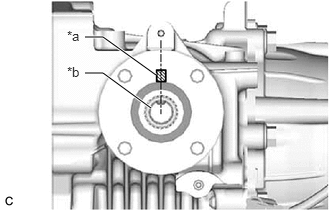
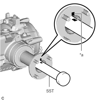
- Align the matchmark on the transfer output shaft companion flange sub-assembly with the transfer driven pinion groove, and then temporarily install the transfer output shaft companion flange sub-assembly to the transfer assembly as shown in the illustration.
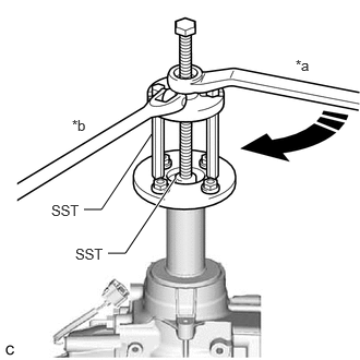
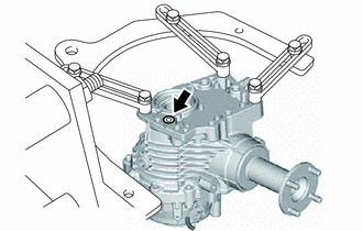
*a Matchmark *b Transfer Driven Pinion - Using SST, install the transfer output shaft companion flange sub-assembly.
*a Turn *b Hold - SST: 09950-30012
- 09951-03010
- 09953-03010
- 09954-03010
- 09955-03030
- SST: 09956-03090
- SST: 09950-30012
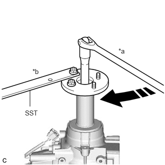
- Using SST, temporarily install a new output shaft companion flange nut to the transfer assembly.
*a Turn *b Hold - SST: 09330-00021
Torque: 140 N.m (1428 kgf/cm, 103 ft.lbf)
WARNING:The total preload may be within the standard even when the transfer output shaft companion flange sub-assembly is loose. If the transfer output shaft companion flange sub-assembly is installed in this state, the vehicle may be damaged or lead to a serious accident.
NOTE:Tighten the output shaft companion flange nut until there is no more looseness in the transfer output shaft companion flange sub-assembly and it turns to the right and left with the same amount of force.
HINT:
After temporarily installing the output shaft companion flange nut, be sure to adjust the preoload.
- Align the matchmark on the transfer output shaft companion flange sub-assembly with the transfer driven pinion groove, and then temporarily install the transfer output shaft companion flange sub-assembly to the transfer assembly as shown in the illustration.
- INSPECT TOTAL PRELOAD
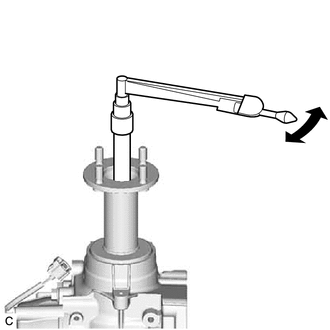
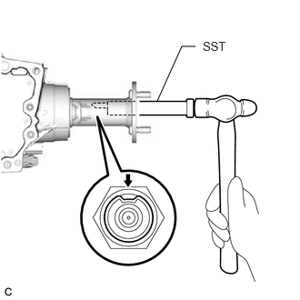
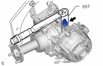
- Using a torque wrench, measure the total preload (starting torque) with the teeth of the transfer driven pinion and transfer ring gear in contact.
HINT:
- The torque wrench should be installed as shown in the illustration.
- For a more accurate measurement, rotate the bearing forward and backward several times before the measurement.
- Use the preload value measured prior to disassembling the transfer assembly as the standard value.
- Adjust within the standard value (Adjustable range within +/- 0.2 N.m of the measured preload value).
- If the preload is not as specified, perform the procedures below.
- If the measured preoload is higher than the standard value:
Replace the rear drive pinion bearing and transfer pinion bearing spacer, and then adjust the preload again.
- If the measured preoload is lower than the standard value:
Tighten the output shaft companion flange nut, and then adjust the preload again.
- If the measured preoload is higher than the standard value:
- Using a torque wrench, measure the total preload (starting torque) with the teeth of the transfer driven pinion and transfer ring gear in contact.
- INSTALL OUTPUT SHAFT COMPANION FLANGE NUT
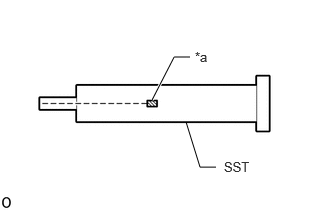
- Place a matchmark on SST as shown in the illustration.
*a Matchmark - SST: 09930-42010
- Install SST aligned with the matchmark on the transfer output shaft companion flange sub-assembly as shown in the illustration.
*a Matchmark - Using SST and a hammer, stake the output shaft companion flange nut.NOTE:
Check that the matchmarks are properly aligned.
- Place a matchmark on SST as shown in the illustration.
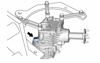
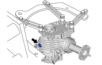
- INSTALL TRANSFER CASE OIL SEAL RH
- Coat the lip of a new transfer case oil seal RH with MP grease.
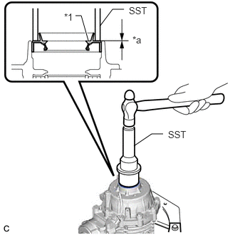
- Using SST and a hammer, tap in the transfer case oil seal RH to the transfer assembly as shown in the illustration.
*1 Transfer Case Oil Seal RH *a Depth - SST: 09223-46011
- SST: 09631-32020
Standard Depth
-0.5 to 0.5 mm (-0.0197 to 0.0197 in.)
NOTE:- Tap the transfer case oil seal RH uniformly so that the transfer case oil seal RH is straight.
- Do not tap the transfer case oil seal RH in too far.
- INSTALL TRANSFER CASE OIL SEAL
See step 5
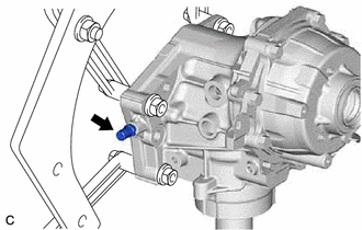
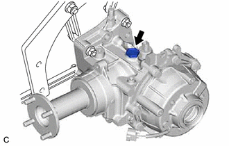
- INSTALL TRANSFER CASE BREATHER PLUG
- INSTALL NO. 1 4 WHEEL DRIVE POSITION SWITCH
- INSTALL TRANSFER FILLER PLUG
- INSTALL TRANSFER DRAIN PLUG
- INSTALL NO. 2 TRANSFER CASE PLUG
- INSTALL NO. 1 TRANSFER CASE PLUG
- INSTALL TRANSFER CASE STRAIGHT PIN
- REMOVE TRANSFER ASSEMBLY
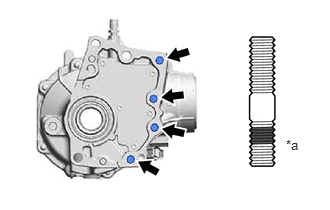
- INSTALL TRANSFER AND TRANSAXLE SETTING STUD BOLT
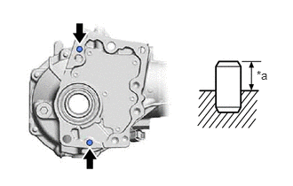
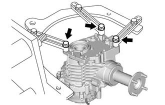
- Clean the 4 bolt holes.
- Using 2 nuts, install 4 new transfer and transaxle setting stud bolts to the transfer assembly at the positions shown in the illustration.
*a Sealed Side Torque: 39.2 N.m (400 kgf/cm, 29 ft.lbf)
NOTE:Install the sealed side of the transfer and transaxle setting stud bolt to the transfer assembly.
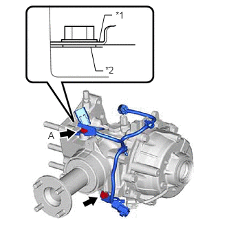
- INSTALL CLUTCH CONTROL SOLENOID WIRE
- Install the 2 wiring harness clamp brackets and clutch control solenoid wire to the transfer assembly with the 2 bolts.
*1 Wiring Harness Clamp Bracket *2 Clutch Control Solenoid Wire Torque: 19.6 N.m (200 kgf/cm, 14 ft.lbf)
HINT:
Tighten the ground of the clutch control solenoid wire together with the bolt (A).
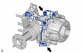
- Connect the 4 clamps and 2 connectors.
- Install the 2 wiring harness clamp brackets and clutch control solenoid wire to the transfer assembly with the 2 bolts.