Inspection [12/2019 - ]: Procedure
- INSPECT MULTI-TERRAIN SELECT SWITCH (NO. 1 PATTERN SELECT SWITCH ASSEMBLY) (for Dial Switch Type)
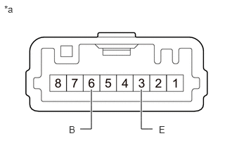
- Measure the resistance according to the value(s) in the table below.
*a Component without harness connected
(Multi-Terrain Select Switch (No. 1 Pattern Select Switch Assembly))Standard Resistance
Tester Connection Condition Specified Condition 6 (B) - 3 (E) NORMAL mode switch being pushed and held 80.4 to 83.6 Ω NORMAL mode switch not pushed 10 kΩ or higher 6 (B) - 3 (E) ROCK & DIRT mode switch being turned and held 580.2 to 603.8 Ω ROCK & DIRT mode switch not turned 10 kΩ or higher 6 (B) - 3 (E) MUD & SAND mode switch being turned and held 2.050 to 2.134 kΩ MUD & SAND mode switch not turned 10 kΩ or higher If the result is not as specified, replace the No. 1 pattern select switch assembly.
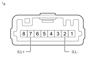
- Apply battery voltage between the terminals of the switch and check the illumination condition of the multi-terrain select switch (No. 1 pattern select switch assembly).
*a Component without harness connected
(Multi-Terrain Select Switch (No. 1 Pattern Select Switch Assembly))Standard
Measurement Condition Specified Condition Battery positive (+) → 7 (ILL+)
Battery negative (-) → 2 (ILL-)Illuminates If the result is not as specified, replace the No. 1 pattern select switch assembly.
- Measure the resistance according to the value(s) in the table below.
- INSPECT CRAWL CONTROL SWITCH ASSEMBLY (for Push Switch Type)
- Measure the resistance according to the value(s) in the table below.
*a Component without harness connected
(Crawl Control Switch Assembly)Standard Resistance
Tester Connection Condition Specified Condition 6 (B) - 3 (E) NORMAL mode switch being pushed and held 80.4 to 83.6 Ω NORMAL mode switch not pushed 10 kΩ or higher 6 (B) - 3 (E) ROCK & DIRT mode switch being pushed and held 580.2 to 603.8 Ω ROCK & DIRT mode switch not pushed 10 kΩ or higher 6 (B) - 3 (E) MUD & SAND mode switch being pushed and held 2.050 to 2.134 kΩ MUD & SAND mode switch not pushed 10 kΩ or higher If the result is not as specified, replace the crawl control switch assembly.
- Apply battery voltage between the terminals of the switch and check the illumination condition of the crawl control switch assembly.
*a Component without harness connected
(Crawl Control Switch Assembly)Standard
Measurement Condition Specified Condition Battery positive (+) → 7 (ILL+)
Battery negative (-) → 2 (ILL-)Illuminates If the result is not as specified, replace the crawl control switch assembly.
- Measure the resistance according to the value(s) in the table below.