Reassembly [12/2019 - 10/2022]: Procedure
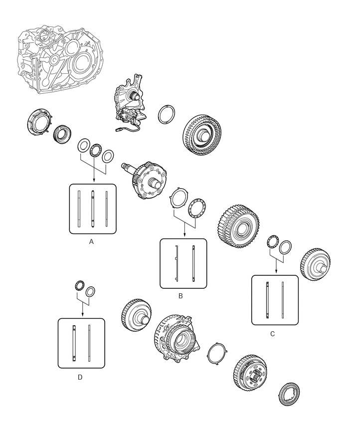
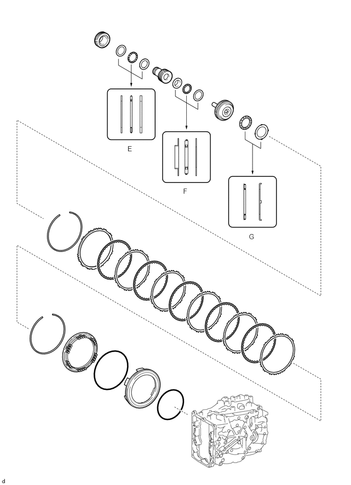
- BEARING POSITION
Check bearing position and installation direction.
Thrust Needle Roller Bearing and Bearing Race Diameter
Mark Front Side Thrust Bearing Race Diameter Inside / Outside
mm (in.)Thrust Bearing Diameter Inside / Outside
mm (in.)Rear Side Thrust Bearing Race Diameter Inside / Outside
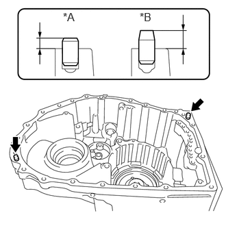
mm (in.)A 32.6 (1.28) / 54.2 (2.13) 31.7 (1.25) / 52.3 (2.06) 31.7 (1.25) / 52.3 (2.06) B 59.8 (2.35) / 77.0 (3.03) 58.3 (2.30) / 75.0 (2.95) - C - 39.2 (1.54) / 52.6 (2.07) 38.1 (1.50) / 50.2 (1.98) D - 33.3 (1.31) / 46.3 (1.82) 34.2 (1.35) / 47.3 (1.86) E 34.4 (1.35) / 48.7 (1.92) 33.2 (1.31) / 47.7 (1.88) 33.2 (1.31) / 47.7 (1.88) F 25.58 (1.01) / 43.7 (1.72) 24.2 (0.953) / 43.7 (1.72) 24.2 (0.953) / 43.7 (1.72) G - 50.5 (1.99) / 74.5 (2.93) 52.8 (2.08) / 76.4 (3.01) - INSTALL AUTOMATIC TRANSMISSION CASE STRAIGHT PIN NOTE:
It is not necessary to remove the automatic transmission case straight pins unless they are being replaced.
HINT:

Serial Number The component manufacturer (AW (AISIN AW) or TMMWV (TOYOTA)) can be determined based on the serial number as described in the following table.
Serial Number Factory ##6######## AW (AISIN AW) ##A######## TMMWV (TOYOTA) - INSTALL COUNTER DRIVEN GEAR FRONT TAPERED ROLLER BEARING (INNER RACE)
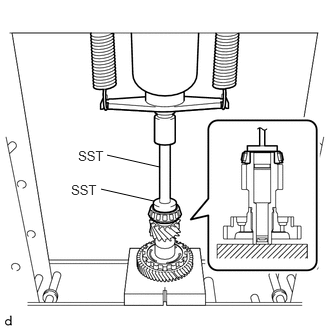
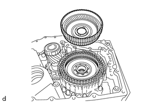
- Using SST and a press, install a new counter driven gear front tapered roller bearing (inner race) to the pinion and counter driven gear sub-assembly.
- SST: 09950-60011
- 09951-00550
- SST: 09950-70010
- 09951-07150
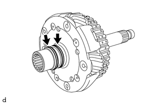
NOTE:Be sure to install the counter driven gear front tapered roller bearing (inner race) so that there is no clearance between the counter driven gear front tapered roller bearing (inner race) and the pinion and counter driven gear sub-assembly. If there is any clearance, the turning torque of the pinion and counter driven gear sub-assembly cannot be measured correctly.
- SST: 09950-60011
- Using SST and a press, install a new counter driven gear front tapered roller bearing (inner race) to the pinion and counter driven gear sub-assembly.
- INSTALL COUNTER DRIVEN GEAR FRONT TAPERED ROLLER BEARING (OUTER RACE)
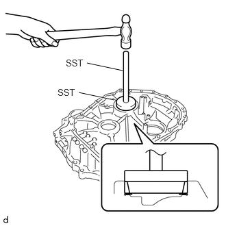
- Using SST and a hammer, install a new counter driven gear front tapered roller bearing (outer race) and pinion and counter driven gear shim to the transaxle housing.
- SST: 09950-60021
- 09951-00780
- SST: 09950-70010
- 09951-07150
NOTE:Be sure to install the counter driven gear front tapered roller bearing (outer race) so that there is no clearance between the counter driven gear front tapered roller bearing (outer race), pinion and counter driven gear shim and the transaxle housing. If there is any clearance, the turning torque of the pinion and counter driven gear sub-assembly cannot be measured correctly.
- SST: 09950-60021
- Using SST and a hammer, install a new counter driven gear front tapered roller bearing (outer race) and pinion and counter driven gear shim to the transaxle housing.
- INSTALL COUNTER DRIVEN GEAR REAR TAPERED ROLLER BEARING (INNER RACE)
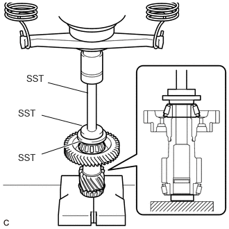
- Using SST and a press, install a new counter driven gear rear tapered roller bearing (inner race) to the pinion and counter driven gear sub-assembly.
- SST: 09506-30012
- SST: 09950-60011
- 09951-00420
- 09951-00550
- SST: 09950-70010
- 09951-07150
NOTE:Be sure to install the counter driven gear rear tapered roller bearing (inner race) so that there is no clearance between the counter driven gear rear tapered roller bearing (inner race) and the pinion and counter driven gear sub-assembly. If there is any clearance, the turning torque of the pinion and counter driven gear sub-assembly cannot be measured correctly.
- Using SST and a press, install a new counter driven gear rear tapered roller bearing (inner race) to the pinion and counter driven gear sub-assembly.
- INSTALL COUNTER DRIVEN GEAR REAR TAPERED ROLLER BEARING (OUTER RACE)
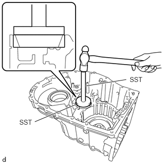
- Using SST and a hammer, install a new counter driven gear rear tapered roller bearing (outer race) to the automatic transaxle case sub-assembly.
- SST: 09950-60021
- 09951-00680
- SST: 09950-70010
- 09951-07150
NOTE:Be sure to install the counter driven gear rear tapered roller bearing (outer race) so that there is no clearance between the counter driven gear rear tapered roller bearing (outer race) and the automatic transaxle case sub-assembly. If there is any clearance, the turning torque of the pinion and counter driven gear sub-assembly cannot be measured correctly.
- SST: 09950-60021
- Using SST and a hammer, install a new counter driven gear rear tapered roller bearing (outer race) to the automatic transaxle case sub-assembly.
- ADJUST FRONT DIFFERENTIAL CASE TAPERED ROLLER BEARING PRELOAD
HINT:
Serial Number The component manufacturer (AW (AISIN AW) or TMMWV (TOYOTA)) can be determined based on the serial number as described in the following table.
Serial Number Factory ##6######## AW (AISIN AW) ##A######## TMMWV (TOYOTA) - Remove any remaining seal packing from the contact surfaces of the transaxle housing and automatic transaxle case sub-assembly.
- Coat the front differential case front tapered roller bearing (inner race) and the front differential case rear tapered roller bearing (inner race) with a sufficient amount of Toyota Genuine ATF WS.
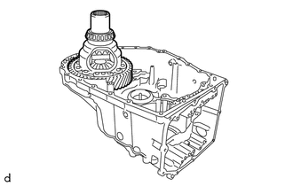
- Install the differential case assembly to the automatic transaxle case sub-assembly.
- Install the transaxle housing to the automatic transaxle case sub-assembly with the 21 bolts (A and B).
Torque: 29.4 N.m (300 kgf/cm, 22 ft.lbf)
Bolt Length
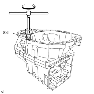
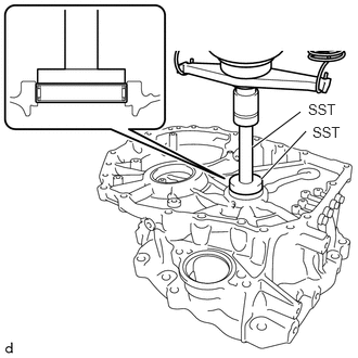
Bolt (A) Bolt (B) 40 mm (1.57 in.) 35 mm (1.38 in.) - Using SST, rotate the differential case assembly 20 times or more to stabilize the bearing.
- SST: 09564-33010
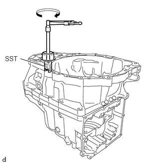
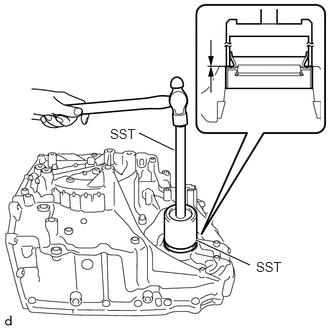
- Using SST and a torque wrench, measure the turning torque of the front differential case tapered roller bearing while rotating SST at 10 rpm.
- SST: 09564-33010
Standard Turning Torque
for AW (AISIN AW) Made
0.69 to 1.02 N.m (8 to 10 kgf/cm, 7 to 9 in.lbf)
for TMMWV Made
0.99 to 1.28 N.m (11 to 13 kgf/cm, 9 to 11 in.lbf)
If the turning torque is not within the specified range, refer to the table below to select a shim so that the turning torque is within the specified range.
Differential Drive Pinion Shim Thickness
Part Number Thickness
mm (in.)Mark 90564-75002 1.10 (0.0433) 50 90564-75003 1.13 (0.0445) 51 90564-75004 1.16 (0.0457) 52 90564-75005 1.19 (0.0469) 53 90564-75006 1.22 (0.0480) 54 90564-75007 1.25 (0.0492) 55 90564-75008 1.28 (0.0504) 56 90564-75009 1.31 (0.0516) 57 90564-75010 1.34 (0.0528) 58 90564-75011 1.37 (0.0539) 59 90564-75012 1.40 (0.0551) 60 90564-75013 1.43 (0.0563) 61 90564-75014 1.46 (0.0575) 62 90564-75015 1.49 (0.0587) 63 90564-75016 1.52 (0.0598) 64 90564-75017 1.55 (0.0610) 65 90564-75018 1.58 (0.0622) 66 90564-75019 1.61 (0.0634) 67 90564-75023 1.64 (0.0646) 68 90564-75024 1.67 (0.0657) 69 90564-75025 1.70 (0.0669) 70 90564-75026 1.73 (0.0681) 71 90564-75027 1.76 (0.0693) 72 90564-75028 1.79 (0.0705) 73 90564-75029 1.82 (0.0717) 74 90564-75030 1.85 (0.0728) 75 90564-75031 1.88 (0.0740) 76 90564-75032 1.91 (0.0752) 77 90564-75033 1.94 (0.0764) 78 90564-75034 1.97 (0.0776) 79 90564-75035 2.00 (0.0787) 80 - Remove the 21 bolts and transaxle housing from the automatic transaxle case sub-assembly.
- ADJUST PINION AND COUNTER DRIVEN GEAR TAPERED ROLLER BEARING PRELOAD
HINT:
Serial Number The component manufacturer (AW (AISIN AW) or TMMWV (TOYOTA)) can be determined based on the serial number as described in the following table.
Serial Number Factory ##6######## AW (AISIN AW) ##A######## TMMWV (TOYOTA) - Coat the counter driven gear front tapered roller bearing (inner race) and the counter driven gear rear tapered roller bearing (inner race) with a sufficient amount of Toyota Genuine ATF WS.
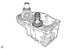
- Install the pinion and counter driven gear sub-assembly to the automatic transaxle case sub-assembly.
- Install the transaxle housing to the automatic transaxle case sub-assembly with the 21 bolts (A and B).
Torque: 29.4 N.m (300 kgf/cm, 22 ft.lbf)
Bolt Length
Bolt (A) Bolt (B) 40 mm (1.57 in.) 35 mm (1.38 in.) - Using SST, rotate the differential case assembly 20 times or more to stabilize the bearing.
- SST: 09564-33010
- Using SST and a torque wrench, measure the turning torque of the pinion and counter driven gear tapered roller bearing while rotating SST at 10 rpm.
- SST: 09564-33010
Standard Turning Torque
for AW (AISIN AW) Made
Front differential case tapered roller bearing preload + 0.99 to 2.26 N.m (11 to 23 kgf/cm, 9 to 20 in.lbf)
for TMMWV Made
Front differential case tapered roller bearing preload + 1.75 to 2.61 N.m (18 to 26 kgf/cm, 16 to 23 in.lbf)
If the turning torque is not within the specified range, refer to the table below to select a shim so that the turning torque is within the specified range.
Pinion and Counter Driven Gear Shim Thickness
Part Number Thickness
mm (in.)Mark 90564-67047 1.19 (0.0469) AA 90564-67048 1.22 (0.0480) AB 90564-67049 1.25 (0.0492) AC 90564-67050 1.28 (0.0504) AD 90564-67051 1.31 (0.0516) AE 90564-67052 1.34 (0.0528) AF 90564-67053 1.37 (0.0539) AG 90564-67054 1.40 (0.0551) AH 90564-67055 1.43 (0.0563) AJ 90564-67056 1.46 (0.0575) AK 90564-67057 1.49 (0.0587) AL 90564-67058 1.52 (0.0598) AM 90564-67059 1.55 (0.0610) AN 90564-67060 1.58 (0.0622) AP 90564-67061 1.61 (0.0634) AR 90564-67062 1.64 (0.0646) AS 90564-67063 1.67 (0.0657) AT 90564-67064 1.70 (0.0669) AU 90564-67065 1.73 (0.0681) AV 90564-67066 1.76 (0.0693) AW 90564-67067 1.79 (0.0705) AX 90564-67068 1.82 (0.0717) AY 90564-67069 1.85 (0.0728) AZ 90564-67071 1.88 (0.0740) BA 90564-67072 1.91 (0.0752) BB 90564-67073 1.94 (0.0764) BC 90564-67074 1.97 (0.0776) BD 90564-67075 2.00 (0.0787) BE 90564-67076 2.03 (0.0799) BF 90564-67077 2.06 (0.0811) BG 90564-67078 2.09 (0.0823) BH 90564-67079 2.12 (0.0835) BJ 90564-67080 2.15 (0.0846) BK 90564-67081 2.18 (0.0858) BL 90564-67082 2.21 (0.0870) BM - Remove the 21 bolts and transaxle housing from the automatic transaxle case sub-assembly.
- Remove the pinion and counter driven gear sub-assembly from the automatic transaxle case sub-assembly.
- Remove the differential case assembly from the automatic transaxle case sub-assembly.
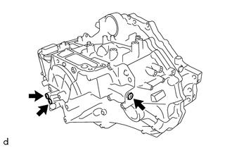
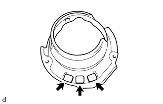
- INSTALL NO. 2 TRANSAXLE CASE PLUG
- Clean the 6 No. 2 transaxle case plugs and 6 installation holes.
- Apply adhesive to 2 or 3 threads on the end of the No. 2 transaxle case plug.
Adhesive
Toyota Genuine Adhesive 1324, Three Bond 1324 or equivalent
NOTE:Make sure to install the No. 2 transaxle case plugs immediately after applying adhesive to prevent foreign matter from attaching to them.
- Using a 6 mm socket hexagon wrench, install the 3 No. 2 transaxle case plugs and 3 new gaskets to the automatic transaxle case sub-assembly.
Torque: 17 N.m (173 kgf/cm, 13 ft.lbf)
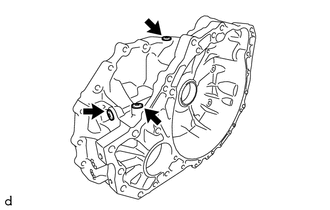
- Using a 6 mm socket hexagon wrench, install the 3 No. 2 transaxle case plugs and 3 new gaskets to the transaxle housing.
Torque: 17 N.m (173 kgf/cm, 13 ft.lbf)
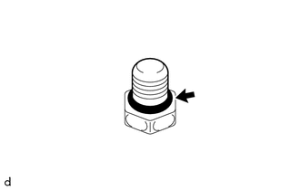
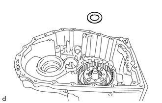
- INSTALL NO. 1 TRANSAXLE CASE PLUG
- Coat 8 new O-rings with Toyota Genuine ATF WS and install them to the 8 No. 1 transaxle case plugs.
- Install the 4 No. 1 transaxle case plugs to the automatic transaxle case sub-assembly.
Torque: 7.4 N.m (75 kgf/cm, 65 in.lbf)
- Install the 4 No. 1 transaxle case plugs to the transaxle housing.
Torque: 7.4 N.m (75 kgf/cm, 65 in.lbf)
- Coat 8 new O-rings with Toyota Genuine ATF WS and install them to the 8 No. 1 transaxle case plugs.
- INSTALL NEEDLE ROLLER BEARING
- INSTALL FRONT DRIVE SHAFT OIL SEAL LH
- INSTALL TRANSAXLE CASE OIL SEAL
- INSTALL FRONT TRANSAXLE CASE OIL SEAL
- Clean and degrease the oil seal press-in surface.
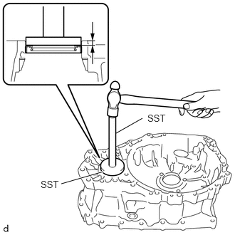
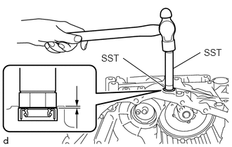
- Using SST and a hammer, install a new front transaxle case oil seal to the transaxle housing.
- SST: 09950-60011
- 09951-00640
- SST: 09950-70010
- 09951-07200
Standard Depth
-0.5 to 0.5 mm (-0.0197 to 0.0197 in.)
- SST: 09950-60011
- Apply MP grease to the lip of the front transaxle case oil seal.
- INSTALL MANUAL VALVE LEVER SHAFT OIL SEAL
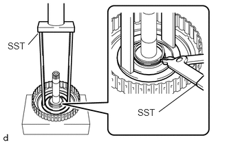
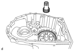
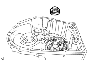
- INSTALL NEEDLE ROLLER BEARING
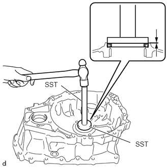
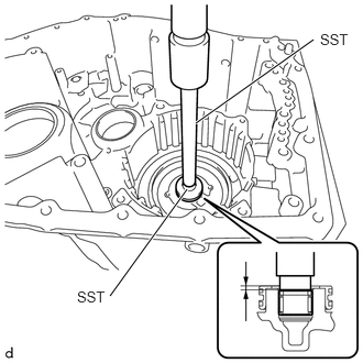
- Using SST and a press, install a new needle roller bearing to the automatic transaxle case sub-assembly.
- SST: 09950-60011
- 09951-00210
- SST: 09950-70010
- 09951-07150
Standard Depth
2.1 to 2.5 mm (0.0827 to 0.0984 in.)
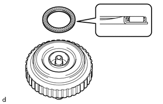
NOTE:Install the needle roller bearing with its supplier name mark facing the front of the automatic transaxle assembly.
- SST: 09950-60011
- Using SST and a press, install a new needle roller bearing to the automatic transaxle case sub-assembly.
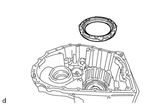
- INSTALL 1ST AND REVERSE BRAKE PISTON
- Apply a light coat of Toyota Genuine ATF WS to 2 new O-rings and install them to the 1st and reverse brake piston.NOTE:
- Make sure to correctly distinguish between the inner side and outer side O-rings.
- Be careful not to damage or twist the O-rings.
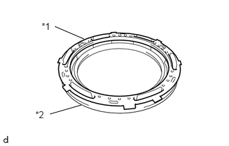
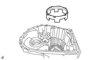
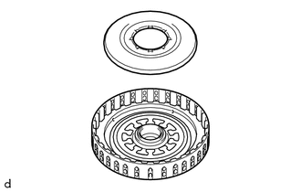
- Set the 1st and reverse brake return spring sub-assembly on the 1st and reverse brake piston.
*1 1st And Reverse Brake Return Spring Sub-assembly *2 1st And Reverse Brake Piston - Install the 1st and reverse brake piston with 1st and reverse brake return spring sub-assembly to the automatic transaxle case sub-assembly.NOTE:
Make sure that the O-rings are not damaged or do not jump out of position during installation.
- Apply a light coat of Toyota Genuine ATF WS to 2 new O-rings and install them to the 1st and reverse brake piston.
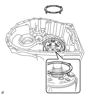
- INSTALL 1ST AND REVERSE BRAKE RETURN SPRING SUB-ASSEMBLY
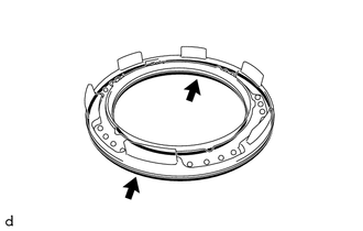
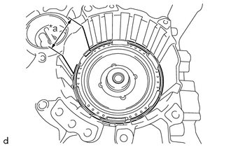
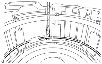
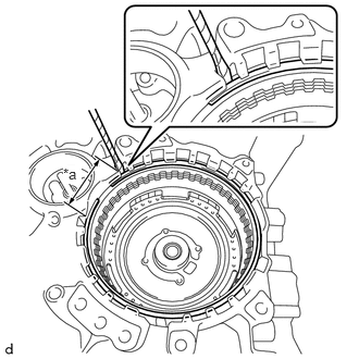
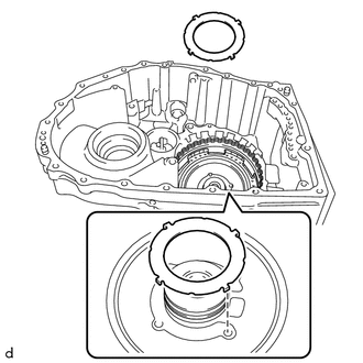
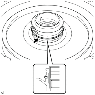
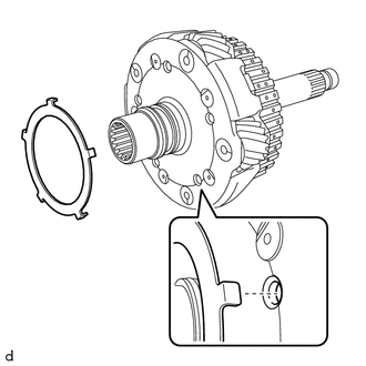
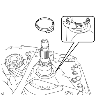
- Set the snap ring on the automatic transaxle case sub-assembly as shown in the illustration.
*a Snap ring opening within this area NOTE:The opening of the snap ring should be within the area shown in the illustration (spline portion).
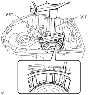
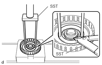
- Place SST on the 1st and reverse brake return spring sub-assembly and compress it with a press.
- SST: 09380-60011
- 09381-06020
- 09381-06050
- 09381-06060
- 09381-06100
- 09381-06110
- SST: 09950-70010
- 09951-07200
NOTE:Stop the press when the 1st and reverse brake return spring sub-assembly is flush with the snap ring groove.
- SST: 09380-60011
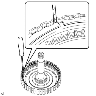
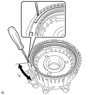
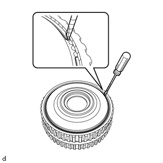
- Using a screwdriver with its tip wrapped with protective tape, install the snap ring into the snap ring groove of the automatic transaxle case sub-assembly.NOTE:
- Be careful not to damage the automatic transaxle case sub-assembly.
- Make sure that the snap ring is installed in the groove of the automatic transaxle case sub-assembly correctly.
- Set the snap ring on the automatic transaxle case sub-assembly as shown in the illustration.
- INSTALL NO. 2 1ST AND REVERSE BRAKE PISTON
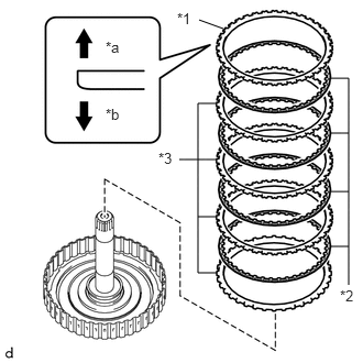
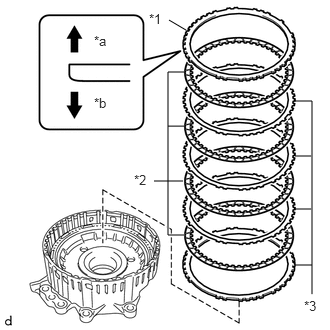
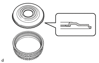
- INSTALL 2ND BRAKE DISC
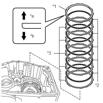
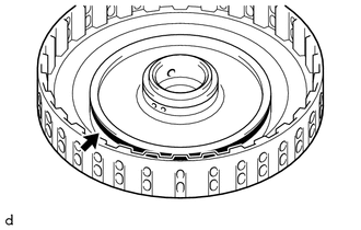
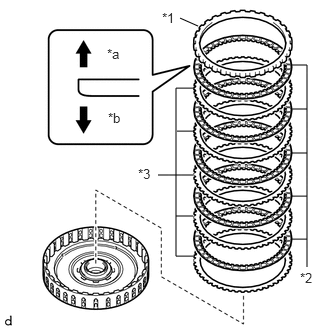
- Install the 5 2nd brake plates, 5 2nd brake discs and 2nd brake flange to the automatic transaxle case sub-assembly.
*1 2nd Brake Flange *2 2nd Brake Disc *3 2nd Brake Plate *a Snap Ring Side *b 2nd Brake Disc Side NOTE:Assemble the 2nd brake flange with its tapered surface facing toward the 2nd brake disc.
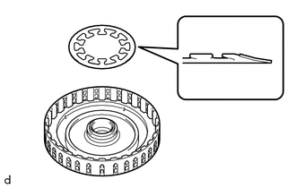
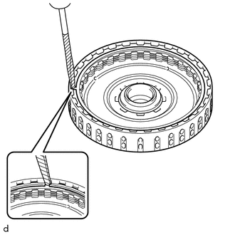
- Using a screwdriver with its tip wrapped with protective tape, install the snap ring to the automatic transaxle case sub-assembly.
*a Snap ring opening within this area NOTE:The opening of the snap ring should be within the area shown in the illustration (spline portion).
- Install the 5 2nd brake plates, 5 2nd brake discs and 2nd brake flange to the automatic transaxle case sub-assembly.
- INSPECT CLEARANCE OF B-2 BRAKE
See step 18
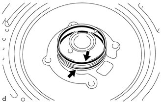
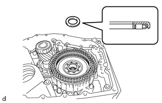
- INSTALL DIRECT CLUTCH DRUM OIL SEAL RING
- Apply a small amount of MP grease to the entire circumference of the direct clutch drum oil seal ring installation groove portion.
HINT:
By applying MP grease, the wobble within the direct clutch drum oil seal ring installation groove will be eliminated, preventing damage to the direct clutch drum oil seal ring at the time of front planetary gear assembly installation.
- Coat 2 new direct clutch drum oil seal rings with Toyota Genuine ATF WS and install them to the automatic transaxle case sub-assembly.NOTE:
While making the spread of the opening of the direct clutch drum oil seal ring as small as possible, install it to the automatic transaxle case sub-assembly. If the ring opening is spread, briefly hold it closed with your fingers to return it to its original condition.
- Apply a small amount of MP grease to the entire circumference of the direct clutch drum oil seal ring installation groove portion.
- INSTALL C-2 CLUTCH PISTON
- Apply a light coat of Toyota Genuine ATF WS to 2 new O-rings and install them to the intermediate shaft sub-assembly.NOTE:
Be careful not to damage or twist the O-rings.
- Apply a light coat of Toyota Genuine ATF WS to the lip seal of the C-2 clutch piston.
- Install the C-2 clutch piston to the intermediate shaft sub-assembly.NOTE:
- Make sure the lip is not cut or folded.
- Be careful not to damage the lip seal of the C-2 clutch piston.
- Apply a light coat of Toyota Genuine ATF WS to 2 new O-rings and install them to the intermediate shaft sub-assembly.
- INSTALL CLUTCH RETURN SPRING SUB-ASSEMBLY
- INSTALL C-2 CLUTCH BALANCER
- Apply a light coat of Toyota Genuine ATF WS to the lip seal of the C-2 clutch balancer.
- Install the C-2 clutch balancer to the intermediate shaft sub-assembly.NOTE:
Be careful not to damage the lip seal of the C-2 clutch balancer.
NOTE:- Make sure the lip is not cut or folded.
- Be careful not to damage the lip seal of the C-2 clutch balancer.
- Place SST on the C-2 clutch balancer and compress the clutch return spring sub-assembly with a press.
- SST: 09387-00020
NOTE:Stop the press when the clutch return spring sub-assembly is flush with the snap ring groove.
- Using SST, install the snap ring to the intermediate shaft sub-assembly.
- SST: 09350-30020
- 09350-07070
NOTE:Make sure that the snap ring is installed in the groove of the intermediate shaft sub-assembly correctly.
- SST: 09350-30020
- INSTALL NO. 2 CLUTCH DISC
- Install the 4 No. 2 clutch plates, 4 No. 2 clutch discs and direct clutch flange to the intermediate shaft sub-assembly.
*1 Direct Clutch Flange *2 No. 2 Clutch Disc *3 No. 2 Clutch Plate *a Snap Ring Side *b No. 2 Clutch Disc Side NOTE:- Be careful during assembly because there are 2 types of No. 2 clutch plate with different thicknesses.
- Assemble the direct clutch flange with its tapered surface facing toward the No. 2 clutch disc.
- Using a screwdriver with its tip wrapped with protective tape, install the snap ring to the intermediate shaft sub-assembly.NOTE:
- Be careful not to damage the intermediate shaft sub-assembly.
- Make sure that the snap ring is installed in the groove of the intermediate shaft sub-assembly correctly.
- Install the 4 No. 2 clutch plates, 4 No. 2 clutch discs and direct clutch flange to the intermediate shaft sub-assembly.
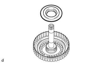
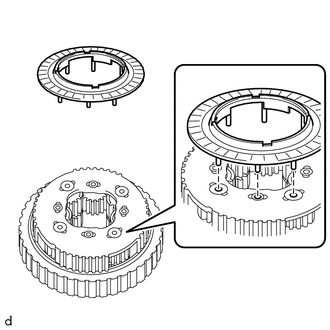
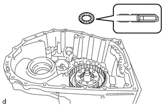
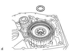
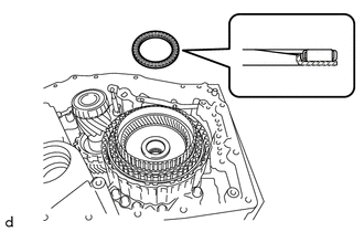
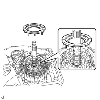
- INSTALL NO. 1 THRUST BEARING RACE
- Coat the No. 1 thrust bearing race with Toyota Genuine ATF WS and install it to the automatic transaxle case sub-assembly.
No. 1 Thrust Bearing Race Diameter
Inside Outside 52.8 mm (2.08 in.) 76.4 mm (3.01 in.) NOTE:Securely insert the claw of the No. 1 thrust bearing race into the hole of the automatic transaxle case sub-assembly.
- Coat the No. 1 thrust bearing race with Toyota Genuine ATF WS and install it to the automatic transaxle case sub-assembly.
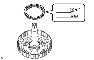
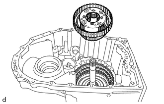
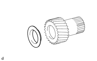
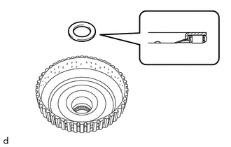
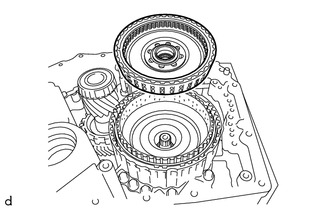
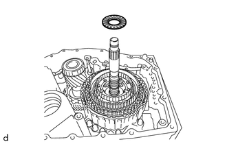
- INSTALL THRUST NEEDLE ROLLER BEARING
- Coat the thrust needle roller bearing with Toyota Genuine ATF WS and install it to the C-2 clutch assembly.
Thrust Needle Roller Bearing Diameter
Inside Outside 50.5 mm (1.99 in.) 74.5 mm (2.93 in.) NOTE:Make sure to assemble the thrust needle roller bearing in the correct direction.
HINT:
When installing the C-2 clutch assembly, if the thrust needle roller bearing falls off, coat the C-2 clutch assembly installation surface with MP grease and install the parts.
- Coat the thrust needle roller bearing with Toyota Genuine ATF WS and install it to the C-2 clutch assembly.
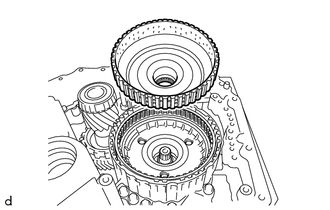
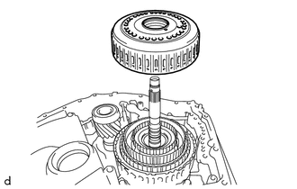
- INSTALL C-2 CLUTCH ASSEMBLY
- INSPECT CLEARANCE OF C-2 CLUTCH
See step 17
- INSTALL NO. 4 PLANETARY CARRIER THRUST WASHER
- Install the No. 4 planetary carrier thrust washer to the rear planetary gear assembly.
HINT:
- Securely insert each protrusion of the No. 4 planetary carrier thrust washer into each indentation of the rear planetary gear assembly.
- When installing the rear planetary gear assembly, if the No. 4 planetary carrier thrust washer falls off, coat the rear planetary gear assembly installation surface with MP grease and install the parts.
- Install the No. 4 planetary carrier thrust washer to the rear planetary gear assembly.
- INSTALL REAR PLANETARY GEAR ASSEMBLY
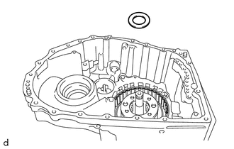
- INSTALL NO. 2 THRUST BEARING RACE
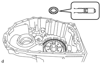
- INSTALL THRUST NEEDLE ROLLER BEARING
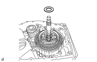
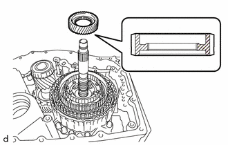
- INSTALL NO. 3 THRUST BEARING RACE
- Coat the No. 3 thrust bearing race with Toyota Genuine ATF WS and install it to the rear planetary sun gear sub-assembly.
No. 3 Thrust Bearing Race Diameter
Inside Outside 25.58 mm (1.01 in.) 43.7 mm (1.72 in.) HINT:
When installing the rear planetary sun gear sub-assembly, if the No. 3 thrust bearing race falls off, coat the rear planetary sun gear sub-assembly installation surface with MP grease and install the parts.
- Coat the No. 3 thrust bearing race with Toyota Genuine ATF WS and install it to the rear planetary sun gear sub-assembly.
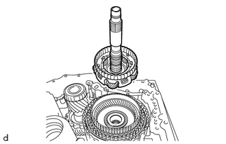
- INSTALL REAR PLANETARY SUN GEAR SUB-ASSEMBLY
- INSTALL THRUST BEARING RACE
- INSTALL THRUST NEEDLE ROLLER BEARING
- INSTALL NO. 4 THRUST BEARING RACE
- INSTALL PLANETARY SUN GEAR SUB-ASSEMBLY
- INSTALL NO. 3 PLANETARY CARRIER THRUST WASHER
- INSTALL NO. 1 BRAKE DISC
- Install the 4 No. 1 brake plates, 4 No. 1 brake discs and No. 1 brake flange to the counter drive gear sub-assembly.
*1 No. 1 Brake Flange *2 No. 1 Brake Disc *3 No. 1 Brake Plate *a Snap Ring Side *b No. 1 Brake Disc Side NOTE:- Be careful during assembly because there are 2 types of No. 1 brake plate with different thicknesses.
- Assemble the No. 1 brake flange with its tapered surface facing toward the No. 1 brake disc.
- Using a screwdriver with its tip wrapped with protective tape, install the snap ring to the counter drive gear sub-assembly.
*a Snap ring opening within this area NOTE:- Be careful not to damage the counter drive gear sub-assembly.
- Make sure that the snap ring is installed in the groove of the counter drive gear sub-assembly correctly.
- The opening of the snap ring should be within the area shown in the illustration (spline portion).
- Install the 4 No. 1 brake plates, 4 No. 1 brake discs and No. 1 brake flange to the counter drive gear sub-assembly.
- INSTALL COUNTER DRIVE GEAR SUB-ASSEMBLY
- Clean and degrease the counter drive gear sub-assembly installation bolts and the 8 bolt holes.NOTE:
If the bolts are tightened without cleaning and degreasing the bolts and bolt holes, the tightening torque will be too high and the counter drive gear sub-assembly or automatic transaxle case sub-assembly may be damaged.
- Coat a new O-ring with Toyota Genuine ATF WS and install it to the automatic transaxle case sub-assembly.
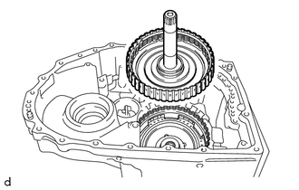
- Install the counter drive gear sub-assembly together with the pinion and counter driven gear sub-assembly to the automatic transaxle case sub-assembly.
- Temporarily install the 8 bolts (A and B).
*a Bolt A *b Bolt B HINT:
Bolt (A) is a hexagon socket head cap bolt.
- Fully tighten the 6 bolts (B).
Torque: 76 N.m (775 kgf/cm, 56 ft.lbf)
- Using a T50 "TORX" socket wrench, fully tighten the 2 bolts (A).
Torque: 31.8 N.m (324 kgf/cm, 23 ft.lbf)
- Clean and degrease the counter drive gear sub-assembly installation bolts and the 8 bolt holes.
- INSPECT CLEARANCE OF B-1 BRAKE
See step 16
- INSTALL PARKING LOCK SLEEVE
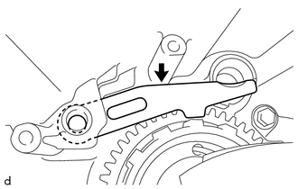
- INSTALL PARKING LOCK PAWL
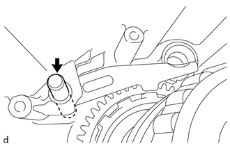
- INSTALL PARKING LOCK PAWL SHAFT
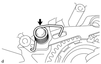
- INSTALL PARKING LOCK PAWL TORSION SPRING
- INSTALL MANUAL VALVE LEVER SHAFT SUB-ASSEMBLY
- INSTALL PARKING LOCK ROD SUB-ASSEMBLY
- INSTALL MANUAL VALVE LEVER SHAFT RETAINER SPRING
- INSTALL PAWL STOPPER PLATE
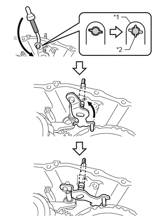
- INSTALL MANUAL VALVE LEVER SUB-ASSEMBLY
- INSTALL MANUAL VALVE LEVER SHAFT SUB-ASSEMBLY
- Coat a new O-ring with Toyota Genuine ATF WS and install it to the manual valve lever shaft sub-assembly.NOTE:
Ensure that the O-ring it not twisted.
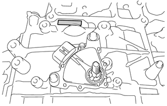
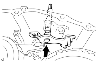
- Align the cutouts of the manual valve lever sub-assembly and manual valve lever shaft sub-assembly, and install the manual valve lever shaft sub-assembly.
HINT:
Installing the manual valve lever shaft sub-assembly to the area shown in the illustration will align the cutouts.
- Secure the manual valve lever shaft sub-assembly to the automatic transaxle case sub-assembly with the bolt.
Torque: 9.8 N.m (100 kgf/cm, 87 in.lbf)
- Coat a new O-ring with Toyota Genuine ATF WS and install it to the manual valve lever shaft sub-assembly.
- INSTALL NO. 5 THRUST BEARING RACE
- INSTALL THRUST NEEDLE ROLLER BEARING
- INSTALL SUN GEAR INPUT HUB SUB-ASSEMBLY
- INSTALL FORWARD CLUTCH PISTON
HINT:
Serial Number The component manufacturer (AW (AISIN AW) or TMMWV (TOYOTA)) can be determined based on the serial number as described in the following table.
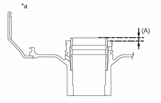
Serial Number Factory ##6######## AW (AISIN AW) ##A######## TMMWV (TOYOTA) - Install Bearing. (for TMMWV Made)
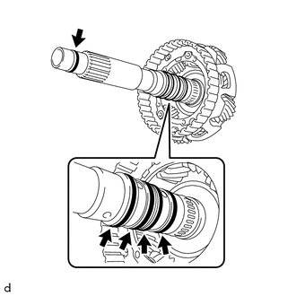
- Measure the length shown in the illustration (A).
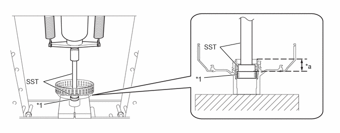
*a Cross Sections of Clutch Drum Sub-assembly - Using a press and SST, press a new needle roller bearing into the clutch drum sub-assembly to the position shown in the illustration.
*1 Needle Roller Bearing - - *a Needle Roller Bearing Press Depth (B) - - - SST: 09950-60011
- 09951-00340
- SST: 09950-70010
- 09951-07100
Needle Roller Bearing Press Depth (B)
Press depth (B) (mm) = Measured value (A) + 17.5 +/- 0.2 (mm)
NOTE:- If the needle roller bearing is pressed beyond the standard position, replace the needle roller bearing with a new one.
- Using a press, press with 6000 N (612 kgf, 1348.9 lbf) or less.
HINT:
Only perform this operation when replacing the needle roller bearing or clutch drum sub-assembly.
- SST: 09950-60011
- Measure the length shown in the illustration (A).
- Apply a light coat of Toyota Genuine ATF WS to a new D-ring and install it to the clutch drum sub-assembly.
HINT:
- Be careful not to damage or twist the D-ring.
- The rounded surface of the D-ring will be on the outer side of the ring groove.
- Apply a light coat of Toyota Genuine ATF WS to a new O-ring and install it to the clutch drum sub-assembly.NOTE:
Be careful not to damage or twist the O-ring.
- Apply a light coat of Toyota Genuine ATF WS to the forward clutch piston and install it to the clutch drum sub-assembly.NOTE:
- Make sure that the O-ring and D-ring are not damaged or do not jump out of position during installation.
- Make sure the lip is not cut or folded.
- Install Bearing. (for TMMWV Made)
- INSTALL REAR CLUTCH PISTON RETURN COMPRESSION SPRING
- INSTALL NO. 1 CLUTCH BALANCER
- Apply a light coat of Toyota Genuine ATF WS to the lip seal of the forward clutch piston.
- Install the No. 1 clutch balancer to the forward clutch piston.NOTE:
Be careful not to damage the lip seal of the forward clutch piston.
- Place SST on the No. 1 clutch balancer and compress the rear clutch piston return compression spring with a press.
- SST: 09387-00020
NOTE:Stop the press when the rear clutch piston return compression spring is flush with the snap ring groove.
- Using SST, install the snap ring to the clutch drum sub-assembly.
- SST: 09350-30020
- 09350-07070
NOTE:Make sure that the snap ring is installed in the groove of the clutch drum sub-assembly correctly.
- SST: 09350-30020
- INSTALL FRONT CLUTCH DISC
- Install the 5 forward multiple disc clutch plates, 5 front clutch discs and forward clutch flange to the clutch drum sub-assembly.NOTE:
- Be careful during assembly because there are 2 types of forward multiple disc clutch plate with different thicknesses.
- Assemble the forward clutch flange with its tapered surface facing toward the front clutch disc.
*1 Forward Clutch Flange *2 Front Clutch Disc *3 Forward Multiple Disc Clutch Plate *a Snap Ring Side *b Front Clutch Disc Side - Using a screwdriver with its tip wrapped with protective tape, install the snap ring to the clutch drum sub-assembly.NOTE:
- Be careful not to damage the clutch drum sub-assembly.
- Make sure that the snap ring is installed in the groove of the clutch drum sub-assembly correctly.
- Install the 5 forward multiple disc clutch plates, 5 front clutch discs and forward clutch flange to the clutch drum sub-assembly.
- INSPECT CLEARANCE OF C-1 CLUTCH
See step 15
- INSTALL C-1 CLUTCH ASSEMBLY
- INSTALL NO. 6 THRUST BEARING RACE
- INSTALL THRUST NEEDLE ROLLER BEARING
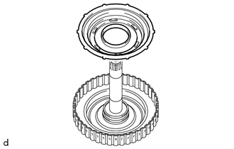
- INSTALL FRONT PLANETARY RING GEAR
- Install the front planetary ring gear flange to the front planetary ring gear.
- Using a screwdriver with its tip wrapped with protective tape, install the snap ring to the front planetary ring gear.NOTE:
Be careful not to damage the front planetary ring gear and front planetary ring gear flange.
- Install the front planetary ring gear with front planetary ring gear flange to the C-1 clutch assembly.
- Install the front planetary ring gear flange to the front planetary ring gear.
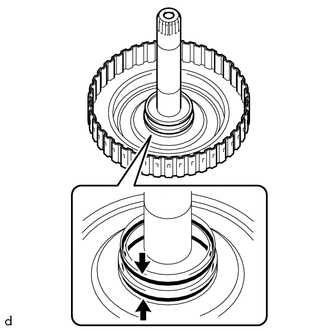
- INSTALL REAR INPUT SHAFT OIL SEAL RING
- Apply a small amount of MP grease to the entire circumference of the rear input shaft oil seal ring installation groove portion.
HINT:
By applying MP grease, the wobble within the rear input shaft oil seal ring installation groove will be eliminated, preventing damage to the rear input shaft oil seal ring at the time of front planetary gear assembly installation.
- Coat 2 new rear input shaft oil seal rings with Toyota Genuine ATF WS and install them to the front planetary gear assembly.NOTE:
While making the spread of the opening of the rear input shaft oil seal ring as small as possible, install it to the front planetary gear assembly. If the ring opening is spread, briefly hold it closed with your fingers to return it to its original condition.
- Apply a small amount of MP grease to the entire circumference of the rear input shaft oil seal ring installation groove portion.
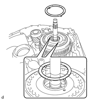
- INSTALL INPUT SHAFT OIL SEAL RING
- Apply a small amount of MP grease to the entire circumference of the input shaft oil seal ring installation groove portion.
HINT:
By applying MP grease, the wobble within the input shaft oil seal ring installation groove will be eliminated, preventing damage to the input shaft oil seal ring at the time of front oil pump assembly and torque converter clutch assembly installation.
- Coat 5 new input shaft oil seal rings with Toyota Genuine ATF WS and install them to the front planetary gear assembly.NOTE:
While making the spread of the opening of the input shaft oil seal ring as small as possible, install it to the front planetary gear assembly. If the ring opening is spread, briefly hold it closed with your fingers to return it to its original condition.
- Apply a small amount of MP grease to the entire circumference of the input shaft oil seal ring installation groove portion.
- INSTALL NO. 7 THRUST BEARING RACE
- Coat the No. 7 thrust bearing race with Toyota Genuine ATF WS and install it to the front planetary gear assembly.
No. 7 Thrust Bearing Race Diameter
Inside Outside 59.8 mm (2.35 in.) 77.0 mm (3.03 in.) NOTE:Securely insert the claw of the No. 7 thrust bearing race into the hole of the front planetary gear assembly.
HINT:
When installing the front planetary gear assembly, if the No. 7 thrust bearing race falls off, coat the front planetary gear assembly installation surface with MP grease and install the parts.
- Coat the No. 7 thrust bearing race with Toyota Genuine ATF WS and install it to the front planetary gear assembly.
- INSTALL THRUST NEEDLE ROLLER BEARING
- INSTALL FRONT PLANETARY GEAR ASSEMBLY
- INSTALL NO. 8 THRUST BEARING RACE
- INSTALL THRUST NEEDLE ROLLER BEARING
- INSTALL NO. 9 THRUST BEARING RACE
- INSTALL PLANETARY SUN GEAR
- INSTALL NO. 2 PLANETARY CARRIER THRUST WASHER
- INSPECT CLEARANCE OF C-4 CLUTCH
See step 14
- INSPECT CLEARANCE OF C-3 CLUTCH
See step 13
- INSTALL C-3 AND C-4 CLUTCH ASSEMBLY
- INSTALL PLANETARY CARRIER THRUST WASHER
- INSTALL FRONT OIL PUMP ASSEMBLY
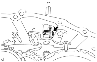
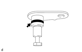
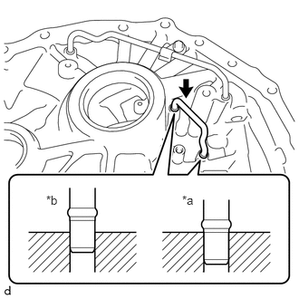
- INSTALL MANUAL DETENT SPRING SUB-ASSEMBLY
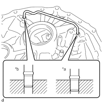
- Install the manual detent spring sub-assembly to the front oil pump assembly with the bolt.
*1 Manual Detent Spring Sub-assembly *2 Manual Valve Lever Shaft Sub-assembly *a Correct *b Incorrect Torque: 9.8 N.m (100 kgf/cm, 87 in.lbf)
NOTE:- Securely insert the claw of the manual detent spring sub-assembly into the hole of the front oil pump assembly.
- Check that the roller portion of the manual detent spring sub-assembly is engaged with the manual valve lever shaft sub-assembly.
- Install the manual detent spring sub-assembly to the front oil pump assembly with the bolt.
- INSTALL OIL PUMP SPROCKET REAR THRUST WASHER
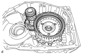
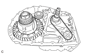
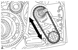
- INSTALL TRANSMISSION DRIVE CHAIN
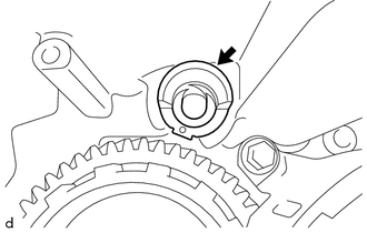
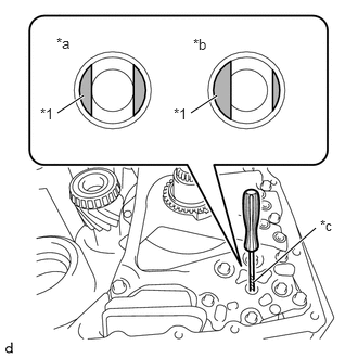
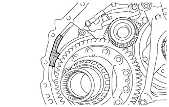
- Using a screwdriver with its tip wrapped with protective tape, align the cutout of the front oil pump drive gear with the position (*a) shown in the illustration.
*1 Front Oil Pump Drive Gear *a Correct *b Incorrect *c Protective Tape NOTE:Do not pry with excessive force when aligning the cutout of the front oil pump drive gear.
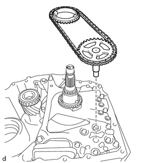
- Install the transmission drive chain together with the transmission oil pump drive sprocket and oil pump drive shaft sub-assembly to the front oil pump assembly.NOTE:
- To avoid damaging the bush of the front oil pump assembly, install the transmission drive chain, transmission oil pump drive sprocket and oil pump drive shaft sub-assembly horizontally relative to the front oil pump assembly.
- Align the cutout of the oil pump drive shaft sub-assembly and the cutout of the front oil pump drive gear, and install the parts.
- Using a screwdriver with its tip wrapped with protective tape, align the cutout of the front oil pump drive gear with the position (*a) shown in the illustration.
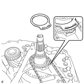
- INSTALL OIL PUMP SPROCKET FRONT THRUST WASHER
- INSTALL CLUTCH DRUM OIL SEAL RING
- Apply a small amount of MP grease to the entire circumference of the clutch drum oil seal ring installation groove portion.
HINT:
By applying MP grease, the wobble within the clutch drum oil seal ring installation groove will be eliminated, preventing damage to the clutch drum oil seal ring at the time of torque converter clutch assembly installation.
- Coat a new clutch drum oil seal ring with Toyota Genuine ATF WS and install it to the front oil pump assembly.NOTE:
While making the spread of the opening of the clutch drum oil seal ring as small as possible, install it to the front oil pump assembly. If the ring opening is spread, briefly hold it closed with your fingers to return it to its original condition.
- Apply a small amount of MP grease to the entire circumference of the clutch drum oil seal ring installation groove portion.
- INSTALL DIFFERENTIAL CASE ASSEMBLY
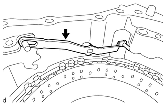
- INSTALL TRANSMISSION LUBE APPLY TUBE
- INSTALL DIFFERENTIAL GEAR LUBE APPLY TUBE
- INSTALL TRANSMISSION OIL CLEANER MAGNET
- INSTALL TRANSAXLE HOUSING OIL SEPARATOR
- INSTALL TRANSAXLE HOUSING
HINT:
Serial Number The component manufacturer (AW (AISIN AW) or TMMWV (TOYOTA)) can be determined based on the serial number as described in the following table.
Serial Number Factory ##6######## AW (AISIN AW) ##A######## TMMWV (TOYOTA) NOTE:When installing the transaxle housing check that the transmission drive chain rotates smoothly.
- Peel off the old seal packing from the transaxle housing and automatic transaxle case sub-assembly installation surface, and clean it.NOTE:
Do not damage the installation surface.
- Clean the 21 bolts and bolt holes in the automatic transaxle case sub-assembly.
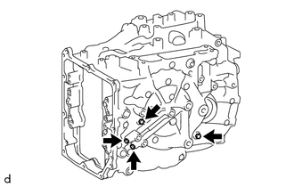
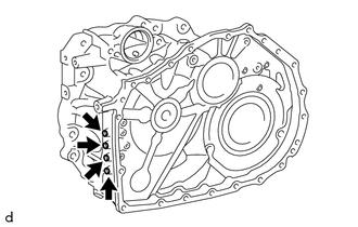
- Clean the inner chamfer of the automatic transaxle case sub-assembly shown in the illustration.
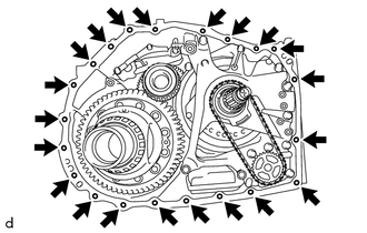
Area to be cleaned - Apply seal packing to the automatic transaxle case sub-assembly as shown in the illustration.
Seal Packing
Toyota Genuine Seal Packing 1281, Three Bond 1281 or equivalent
Standard Seal Diameter
1.8 mm (0.0709 in.)
NOTE:After applying seal packing, install the transaxle housing within 3 minutes and tighten the bolts within 20 minutes of applying the seal packing.
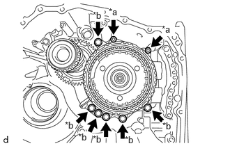
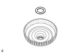
- Coat 5 new transaxle case gaskets with Toyota Genuine ATF WS and install them to the front oil pump assembly.
*1 Transaxle Case Gaskets *2 O-ring - Coat a new O-ring with Toyota Genuine ATF WS and install it to the automatic transaxle case sub-assembly.
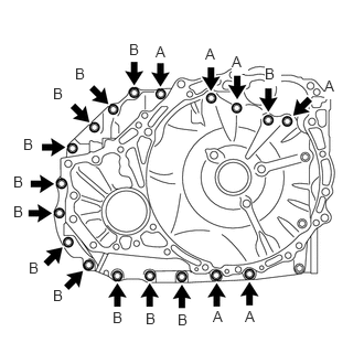
- for TMMWV Made:
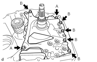
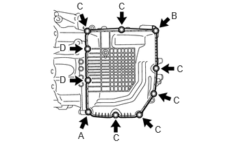
- Install the transaxle housing to the automatic transaxle case sub-assembly with the 6 bolts (A) and 12 bolts (B).
Bolt (A) and (B)
Torque: 29.4 N.m (300 kgf/cm, 22 ft.lbf)
Bolt Length
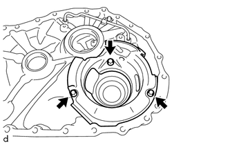
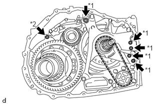
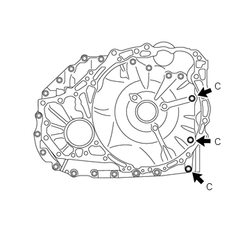
Bolt (A) Bolt (B) 40 mm (1.57 in.) 35 mm (1.38 in.) - Apply adhesive to 2 or 3 threads on the ends of the 3 bolts (C).
*a Adhesive Bolt Length
40 mm (1.57 in.)
Adhesive
Toyota Genuine Adhesive 1324, Three Bond 1324 or equivalent
NOTE:Make sure to install the bolts immediately after applying adhesive to prevent foreign matter from attaching to them.
HINT:
The 3 bolts (C) are in the locations shown in the following step.
- Install the 3 bolts (C).
Bolt (C)
Torque: 22.7 N.m (231 kgf/cm, 17 ft.lbf)
- Install the transaxle housing to the automatic transaxle case sub-assembly with the 6 bolts (A) and 12 bolts (B).
- for AW (AISIN AW) Made:
- Peel off the old seal packing from the transaxle housing and automatic transaxle case sub-assembly installation surface, and clean it.
- INSPECT INPUT SHAFT END PLAY
See step 12
- INSTALL TRANSMISSION REVOLUTION SENSOR (NC)
- INSTALL TRANSMISSION REVOLUTION SENSOR (NT)
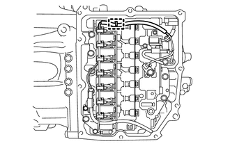
- INSTALL TRANSMISSION VALVE BODY ASSEMBLY
- Coat 2 new transaxle case gaskets with Toyota Genuine ATF WS and install them to the automatic transaxle case sub-assembly.
*1 Transaxle Case Gasket *2 No. 1 Front Oil Pump Cover Gasket *3 No. 2 Front Oil Pump Cover Gasket - Coat a new transaxle case gasket with Toyota Genuine ATF WS and install it to the counter drive gear sub-assembly.
- Coat a new transaxle case gasket with Toyota Genuine ATF WS and install it to the front oil pump assembly.
- Coat a new No. 1 front oil pump cover gasket with Toyota Genuine ATF WS and install it to the front oil pump assembly.
- Coat a new No. 2 front oil pump cover gasket with Toyota Genuine ATF WS and install it to the front oil pump assembly.
- Align the slit portion of the manual valve and the manual valve lever sub-assembly as shown in the illustration, and install the transmission valve body assembly to the automatic transaxle case sub-assembly with the 9 bolts.
*1 Manual Valve *2 Manual Valve Lever Sub-assembly Torque: 10.8 N.m (110 kgf/cm, 8 ft.lbf)
NOTE:Be careful that the transmission revolution sensor (NC) wire is not pinched.
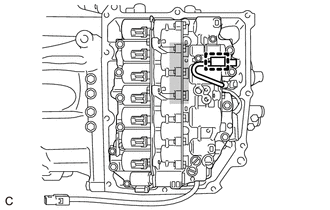
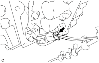
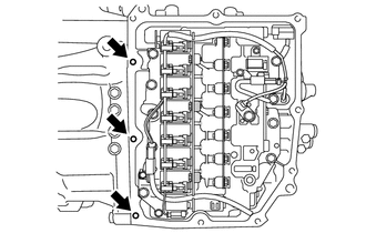
- Engage the clamp to connect the transmission revolution sensor (NC) wire connector.
Do not let transmission revolution sensor (NC) wire ride up over this area. NOTE:To prevent it from being pinched between the transmission valve body assembly and transmission case side cover, do not let the transmission revolution sensor (NC) wire ride up over the area shown in the illustration.
- Coat 2 new transaxle case gaskets with Toyota Genuine ATF WS and install them to the automatic transaxle case sub-assembly.
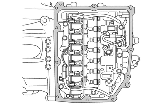
- INSTALL TRANSMISSION WIRE
- Coat the O-ring of the transmission wire with Toyota Genuine ATF WS.
- Install the transmission wire to the automatic transaxle case sub-assembly with the bolt.
Torque: 5.4 N.m (55 kgf/cm, 48 in.lbf)
- Connect the transmission revolution sensor (NT) connector and transmission revolution sensor (NC) connector.
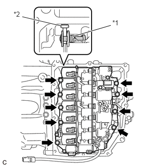
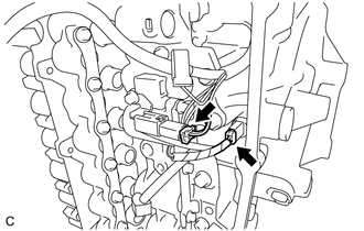
- Install the temperature sensor to the transmission valve body assembly with the bolt and temperature sensor clamp.
Torque: 10.8 N.m (110 kgf/cm, 8 ft.lbf)
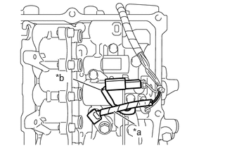
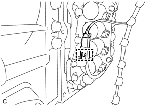
NOTE:To prevent it from being pinched between the transmission valve body assembly and the transmission case side cover, pass the transmission revolution sensor (NC) wire under the transmission wire (temperature sensor wire) as shown in the illustration.
*a Transmission Wire (Temperature Sensor Wire) *b Transmission Revolution Sensor (NC) Wire - Engage the clamp to connect the transmission wire (oil pump with solenoid assembly) to the solenoid lock plate.
- Connect the transmission wire connector.
- Engage the wire harness clamp to connect the transmission wire (oil pump with solenoid assembly).
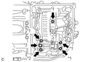
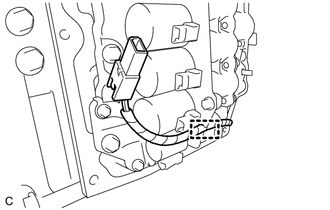
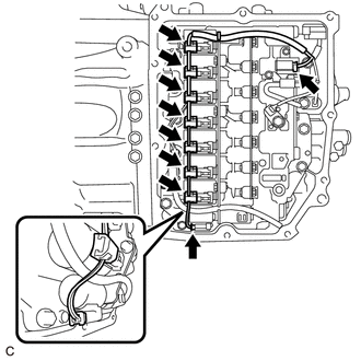
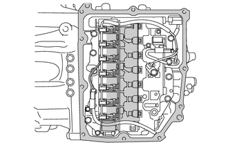
- Connect the 9 solenoid valve connectors as shown in the illustration.NOTE:
Do not let transmission wire protrude into this area. - To prevent it from being pinched between the transmission valve body assembly and the transmission case side cover, do not let the transmission wire ride up over the area shown in the illustration.
- To prevent it from being pinched between the transmission case side cover and the automatic transaxle case sub-assembly, do not let the transmission wire protrude toward the transmission case side cover installation surface.
- Engage the clamp to connect the transmission wire to the solenoid lock plate.
- Coat the O-ring of the transmission wire with Toyota Genuine ATF WS.
- INSTALL TRANSMISSION CASE SIDE COVER (for AW (AISIN AW) Made)
HINT:
Serial Number The component manufacturer (AW (AISIN AW) or TMMWV (TOYOTA)) can be determined based on the serial number as described in the following table.
Serial Number Factory ##6######## AW (AISIN AW) ##A######## TMMWV (TOYOTA) - Clean the transmission case side cover installation surface of the automatic transaxle case sub-assembly.
Area to be cleaned NOTE:Completely remove any oil or grease from the contact surfaces of the automatic transaxle case sub-assembly.
- Temporarily install a new transmission case side cover to the automatic transaxle case sub-assembly with the 2 bolts ((A) and (B)).NOTE:
To avoid damaging the gasket, prevent it from contacting the surrounding area during installation procedures.
- Temporarily install the 8 bolts (C).
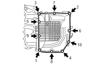
- Fully tighten the 10 bolts in the order shown in the illustration.
 Courtesy of © TOYOTA, LICENSE AGREEMENT TMS1002
Torque: 7.0 N.m (71 kgf/cm, 62 in.lbf)
- Clean the transmission case side cover installation surface of the automatic transaxle case sub-assembly.
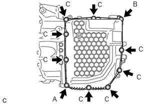
- INSTALL TRANSMISSION CASE SIDE COVER (for TMMWV Made)
HINT:
Serial Number The component manufacturer (AW (AISIN AW) or TMMWV (TOYOTA)) can be determined based on the serial number as described in the following table.
Serial Number Factory ##6######## AW (AISIN AW) ##A######## TMMWV (TOYOTA) Area to be cleaned Clean the transmission case side cover installation surface of the automatic transaxle case sub-assembly.
NOTE:Completely remove any oil or grease from the contact surfaces of the automatic transaxle case sub-assembly.
- Clean the 3 bolt holes shown in the illustration.
- Apply adhesive to 2 or 3 threads on the end of the bolt (A) and 2 bolts (D).
Adhesive
Toyota Genuine Adhesive 1324, Three Bond 1324 or equivalent
NOTE:Make sure to install the bolts immediately after applying adhesive to prevent foreign matter from attaching to them.
*a Adhesive HINT:
The bolt (A) and 2 bolts (D) are in the locations shown in the following step.
- Temporarily install a new transmission case side cover to the automatic transaxle case sub-assembly with the 2 bolts ((A) and (B)).NOTE:
- Bolt (A) is the adhesive-coated bolt.
- To avoid damaging the gasket, prevent it from contacting the surrounding area during installation procedures.
- Temporarily install the 6 bolts (C) and 2 bolts (D).NOTE:
Bolts (D) are the adhesive-coated bolts.
- Fully tighten the 10 bolts in the order shown in the illustration.
 Courtesy of © TOYOTA, LICENSE AGREEMENT TMS1002
Bolt (A) and Bolt (D)
Torque: 6.5 N.m (66 kgf/cm, 58 in.lbf)
Bolt (B) and Bolt (C)
Torque: 7.0 N.m (71 kgf/cm, 62 in.lbf)
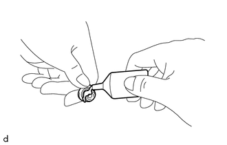
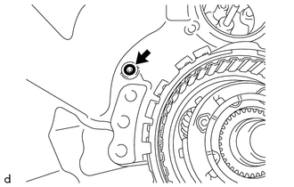
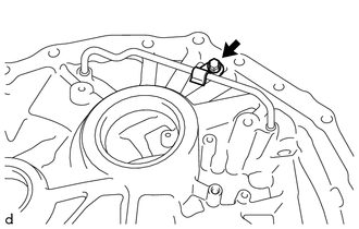
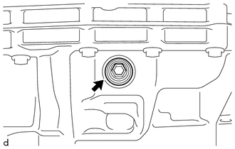
- INSTALL NO. 1 BREATHER PLUG (ATM)
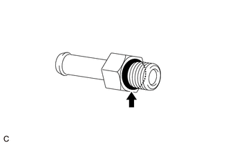
- Coat the O-ring portion of a new No. 1 breather plug (ATM) with Toyota Genuine ATF WS.
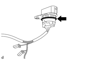
- Engage each claw to install the No. 1 breather plug (ATM) to the automatic transaxle case sub-assembly.
*a Indented Portion *b Detent Aligned NOTE:Securely push in the automatic transaxle case sub-assembly until the No. 1 breather plug (ATM) is engaged.
HINT:
Install the No. 1 breather plug (ATM) with its detent aligned with the indented portion of the automatic transaxle case sub-assembly.
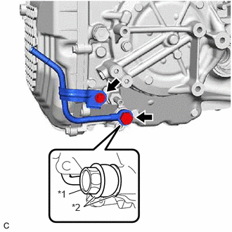
- INSTALL OIL COOLER OUTLET UNION OR ELBOW
- Coat a new O-ring with Toyota Genuine ATF WS and install it to the oil cooler outlet union or elbow.NOTE:
Ensure that the O-ring is not twisted.
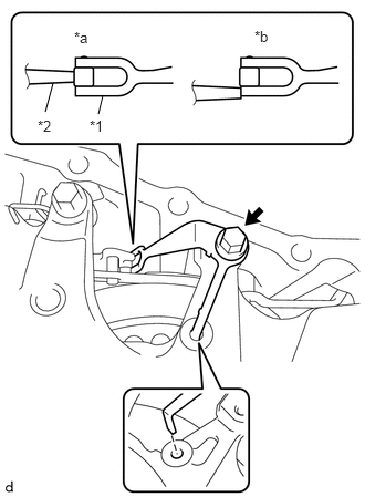
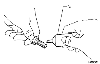
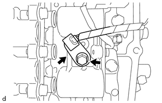
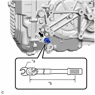
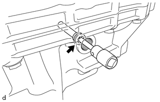
- Using a 19 mm union nut wrench, install the oil cooler outlet union or elbow to the automatic transaxle case sub-assembly.
*a Union Nut Wrench *b Torque Wrench Fulcrum Length Specified tightening torque
Torque: 31.1 N.m (317 kgf/cm, 23 ft.lbf)
HINT:
- Calculate the torque wrench reading when changing the fulcrum length of the torque wrench.
Refer to PRECAUTION [12/2019 - 11/2023]
- When using a 19 mm union nut wrench (fulcrum length of 30 mm (1.18 in.)) + torque wrench (fulcrum length of 180 mm (7.09 in.)):
26.7 N.m (272 kgf/cm, 20 ft.lbf)
- Calculate the torque wrench reading when changing the fulcrum length of the torque wrench.
- Coat a new O-ring with Toyota Genuine ATF WS and install it to the oil cooler outlet union or elbow.
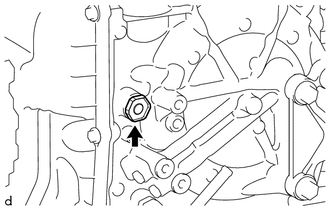
- INSTALL OIL COOLER UNION SUB-ASSEMBLY
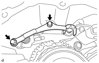
- Pass the oil cooler union sub-assembly through 2 new gaskets and temporarily install it to the automatic transaxle case sub-assembly.
*1 Oil Cooler Union Bolt *2 Gasket - Temporarily install the oil cooler union sub-assembly bracket portion to the automatic transaxle case sub-assembly with the bolt.
- Fully tighten the oil cooler union bolt.
Torque: 22.6 N.m (230 kgf/cm, 17 ft.lbf)
- Fully tighten the bolt.
Torque: 12 N.m (122 kgf/cm, 9 ft.lbf)
- Pass the oil cooler union sub-assembly through 2 new gaskets and temporarily install it to the automatic transaxle case sub-assembly.
- INSTALL NO. 1 TRANSMISSION OIL FILLER TUBE
- INSTALL OVERFLOW PLUG
- INSTALL REFILL PLUG
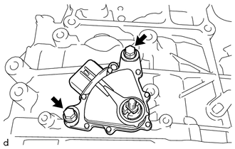
- INSTALL PARK/NEUTRAL POSITION SWITCH ASSEMBLY
- Temporarily install the park/neutral position switch assembly to the automatic transaxle case sub-assembly with the 2 bolts.
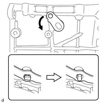
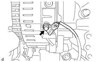
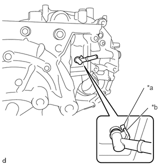
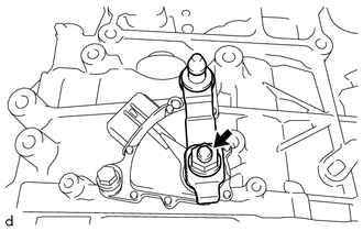
- Temporarily install the transmission control shaft lever to the manual valve lever shaft sub-assembly.
- Turn the transmission control shaft lever clockwise until it stops, then turn it counterclockwise 2 notches.
*a P Position *b N Position - Remove the transmission control shaft lever from the manual valve lever shaft sub-assembly.
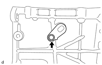
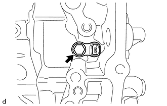
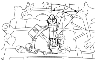
- Align the protrusion with the neutral basic line.
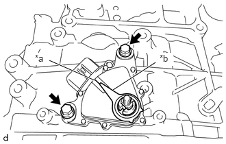
*a Neutral Basic Line *b Protrusion - Hold the park/neutral position switch assembly in that position and tighten the 2 bolts.
Torque: 5.4 N.m (55 kgf/cm, 48 in.lbf)
- Temporarily install the park/neutral position switch assembly to the automatic transaxle case sub-assembly with the 2 bolts.
- INSTALL TRANSMISSION CONTROL SHAFT LEVER