Removal [12/2019 - 10/2022]: Procedure
- REMOVE FRONT WHEEL RH
Refer to REMOVAL [12/2019 - ]
- REMOVE FRONT FENDER APRON SEAL RH
Refer to PROCEDURE - Step 16 [12/2019 - 09/2020] , or refer to PROCEDURE - Step 16 [09/2020 - 10/2022]
- REMOVE V-BANK COVER SUB-ASSEMBLY
Refer to PROCEDURE - Step 23 [12/2019 - 09/2020] , or refer to PROCEDURE - Step 23 [09/2020 - 10/2022]
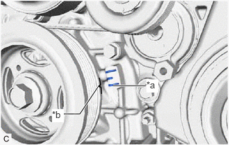
- REMOVE CAMSHAFT TIMING OIL CONTROL SOLENOID ASSEMBLY (for Exhaust Side of Bank 2)
See step 2
- SET NO. 1 CYLINDER TO TDC/COMPRESSION
- Turn the crankshaft pulley clockwise until its timing mark (cutout) is aligned with the timing mark on the timing chain cover assembly as shown in the illustration.
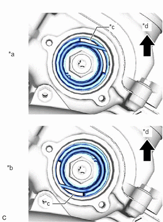
*a Timing Mark *b Timing Mark (Cutout) - Check that the cutout of the camshaft timing gear assembly is at the top.
*a Correct *b Incorrect *c Cutout *d Up HINT:
If the cutout of the camshaft timing gear assembly is not at the top, turn the crankshaft 360° clockwise and align the timing mark (cutout) of the crankshaft pulley with the timing mark on the timing chain cover assembly again.
- Turn the crankshaft pulley clockwise until its timing mark (cutout) is aligned with the timing mark on the timing chain cover assembly as shown in the illustration.
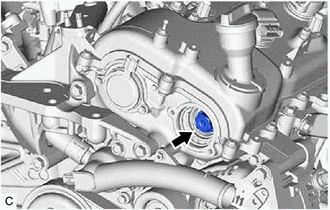
- REMOVE CAMSHAFT TIMING GEAR BOLT