Installation [10/2022 - ]: Procedure
- INSTALL SPRING SEAT SUB-ASSEMBLY
HINT:
Perform this procedure only when replacement of the spring seat sub-assembly is necessary.
- Install the spring seat sub-assembly to the vehicle with the 3 bolts.
Torque: 50 N.m (510 kgf/cm, 37 ft.lbf)
- Install the spring seat sub-assembly to the vehicle with the 3 bolts.
- INSTALL REAR UPPER COIL SPRING INSULATOR
- Install the rear upper coil spring insulator to the spring seat sub-assembly.
- INSTALL REAR LOWER COIL SPRING INSULATOR
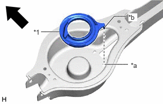
- for LH Side:
- Install the rear lower coil spring insulator LH to the rear No. 2 suspension arm assembly LH.
*1 Rear Lower Coil Spring Insulator LH *a Guide Hole *b Protrusion 
Front of the Vehicle NOTE:Securely insert the protrusion of the rear lower coil spring insulator LH into the guide hole of the rear No. 2 suspension arm assembly LH.
- Install the rear lower coil spring insulator LH to the rear No. 2 suspension arm assembly LH.
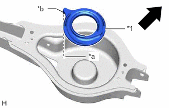
- for RH Side:
- Install the rear lower coil spring insulator RH to the rear No. 2 suspension arm assembly RH.
*1 Rear Lower Coil Spring Insulator RH *a Guide Hole *b Protrusion Front of the Vehicle NOTE:Securely insert the protrusion of the rear lower coil spring insulator RH into the guide hole of the rear No. 2 suspension arm assembly RH.
- Install the rear lower coil spring insulator RH to the rear No. 2 suspension arm assembly RH.
- for LH Side:
- INSTALL REAR COIL SPRING
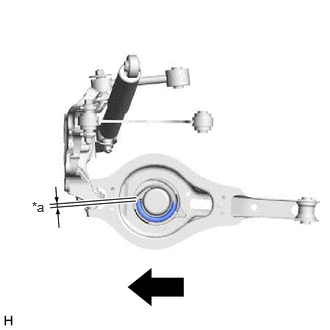
- for LH Side:
- Set the rear coil spring LH to the rear No. 2 suspension arm assembly LH.
*a 20 mm (0.787 in.) or less Outside of the Vehicle NOTE:- The larger diameter end must face upward.
- Set the rear coil spring so that its lower end is within the range shown in the illustration.
- Install the rear lower coil spring insulator LH so that the dimension between the stopper and lower end of the rear coil spring LH is 20 mm (0.787 in.) or less.
- Set the rear coil spring LH to the rear No. 2 suspension arm assembly LH.
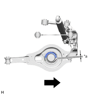
- for RH Side:
- Set the rear coil spring RH to the rear No. 2 suspension arm assembly RH.
*a 20 mm (0.787 in.) or less Outside of the Vehicle NOTE:- The larger diameter end must face upward.
- Set the rear coil spring so that its lower end is within the range shown in the illustration.
- Install the rear lower coil spring insulator RH so that the dimension between the stopper and lower end of the rear coil spring RH is 20 mm (0.787 in.) or less.
- Set the rear coil spring RH to the rear No. 2 suspension arm assembly RH.
- Using a jack and wooden block, slowly jack up the rear No. 2 suspension arm assembly and then temporarily install the rear No. 2 suspension arm assembly to the rear axle carrier sub-assembly with the bolt and nut.WARNING:
Do not jack up the rear No. 2 suspension arm assembly too high as the vehicle may fall.
NOTE:- Because the nut has its own stopper, do not turn the nut. Tighten the bolt with the nut secured.
- When jacking up the rear No. 2 suspension arm assembly, be sure to jack it up slowly.
- Make sure to perform this operation with the vehicle kept as low as possible.
- Insert the bolt with the threaded end facing the front of the vehicle.
- for LH Side:
- STABILIZE SUSPENSION
See step 3
- INSTALL REAR NO. 2 SUSPENSION ARM ASSEMBLY
- Install the rear No. 2 suspension arm assembly (rear axle carrier sub-assembly side) with the bolt.
See step 8
- Install the rear No. 2 suspension arm assembly (rear axle carrier sub-assembly side) with the bolt.
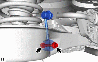
- CONNECT REAR STABILIZER LINK ASSEMBLY
- Connect the rear stabilizer link assembly to the rear No. 2 suspension arm assembly with the bolt and nut.
Torque: 70 N.m (714 kgf/cm, 52 ft.lbf)
NOTE:- Insert the bolt with the threaded end facing the front of the vehicle.
- Because the nut has its own stopper, do not turn the nut. Tighten the bolt with the nut secured.
- Connect the rear stabilizer link assembly to the rear No. 2 suspension arm assembly with the bolt and nut.
- INSTALL REAR SUSPENSION ARM COVER
See step 9
- INSTALL TAIL EXHAUST PIPE ASSEMBLY (for RH Side)
for A25A-FXS: Refer to INSTALLATION [10/2022 - ]
for T24A-FTS: Refer to INSTALLATION [10/2022 - ]
- INSTALL REAR WHEEL
Refer to PROCEDURE - Step 1
- INSTALL REAR NO. 2 SUSPENSION ARM ASSEMBLY
- Install the rear No. 2 suspension arm assembly (rear suspension member sub-assembly side) with the nut.
See step 12
- Install the rear No. 2 suspension arm assembly (rear suspension member sub-assembly side) with the nut.
- INSPECT AND ADJUST REAR WHEEL ALIGNMENT
Refer to ADJUSTMENT [10/2022 - 11/2023] , or refer to ADJUSTMENT [11/2023 - 11/2024] , or refer to ADJUSTMENT [11/2024 - ]
- INSPECT FOR EXHAUST GAS LEAK (for RH Side)
for A25A-FXS: Refer to PROCEDURE - Step 6
for T24A-FTS: Refer to PROCEDURE - Step 3
- PERFORM INITIALIZATION
Parking Assist Monitor System Refer to CALIBRATION [10/2022 - ] Panoramic View Monitor System Refer to CALIBRATION [10/2022 - 11/2023] , or refer to CALIBRATION [11/2023 - ] Lighting System (EXT) (w/ AFS) Refer to INITIALIZATION [12/2019 - 11/2023] , or refer to INITIALIZATION [11/2023 - ]