Installation [12/2019 - 10/2022]: Procedure
- TEMPORARILY INSTALL REAR NO. 1 SUSPENSION ARM ASSEMBLY
- for Gasoline Model 2WD:
- for Gasoline Model AWD:
- for HV Model:
- Remove the bolt, nut and rear lower suspension member stopper.
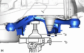
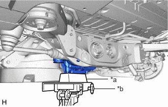
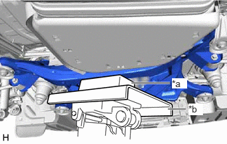
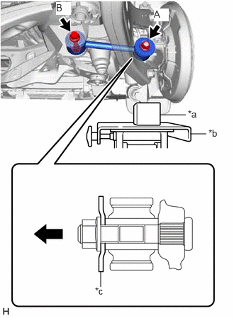
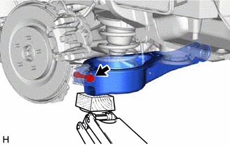
- Using a transmission jack and a wooden block, support the rear axle carrier sub-assembly.
*a Wooden Block *b Jack *c Spacer 
Front of the Vehicle - Temporarily install the rear No. 1 suspension arm assembly to the rear axle carrier sub-assembly with the spacer and nut (A).NOTE:
Be sure to install the rear No. 1 suspension arm assembly with the spacer facing in the correct direction as shown in the illustration.
- Temporarily install the rear No. 1 suspension arm assembly to the rear suspension member sub-assembly with the bolt (B) and nut.NOTE:
- Because the nut has its own stopper, do not turn the nut. Tighten the bolt with the nut secured.
- Insert the bolt with the threaded end facing the rear of the vehicle.
- Install the rear lower suspension member stopper with the bolt and nut.
Bolt
Torque: 158 N.m (1611 kgf/cm, 117 ft.lbf)
Nut
Torque: 32 N.m (326 kgf/cm, 24 ft.lbf)
- Install the No. 2 parking brake wire assembly to the rear lower suspension member stopper with the nut.
Torque: 8.5 N.m (87 kgf/cm, 75 in.lbf)
- TEMPORARILY INSTALL REAR NO. 2 SUSPENSION ARM ASSEMBLY
- Temporarily install the rear No. 2 suspension arm assembly to the rear suspension member sub-assembly with the rear No. 2 suspension camber adjust cam, rear suspension toe adjust cam sub-assembly and the nut.NOTE:
- Insert the rear suspension toe adjust cam sub-assembly from the rear of the vehicle.
- When tightening the nut, keep the rear suspension toe adjust cam sub-assembly from rotating.
- Temporarily install the rear No. 2 suspension arm assembly to the rear suspension member sub-assembly with the rear No. 2 suspension camber adjust cam, rear suspension toe adjust cam sub-assembly and the nut.
- INSTALL REAR LOWER COIL SPRING INSULATOR
See step 3
- INSTALL REAR COIL SPRING
See step 4
- CONNECT REAR STABILIZER LINK ASSEMBLY
See step 7
- STABILIZE SUSPENSION
See step 3
- INSTALL REAR NO. 1 SUSPENSION ARM ASSEMBLY
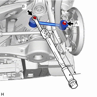
- Using a ball joint lock nut wrench, fully tighten the rear No. 1 suspension arm assembly with the bolt (B).
Specified tightening torque
Torque: 125 N.m (1275 kgf/cm, 92 ft.lbf)
NOTE:Because the nut has its own stopper, do not turn the nut. Tighten the bolt with the nut secured.
HINT:
- Calculate the torque wrench reading when changing the fulcrum length of the torque wrench.
Refer to PRECAUTION [12/2019 - 11/2023]
- When using a ball joint lock nut wrench (fulcrum length of 150 mm (5.91 in.)) + torque wrench (fulcrum length of 400 mm (1.31 ft.)):
91 N.m (928 kgf/cm, 67 ft.lbf)
*a Torque Wrench Fulcrum Length - Calculate the torque wrench reading when changing the fulcrum length of the torque wrench.
- Fully tighten the rear No. 1 suspension arm assembly with the nut (A).
Torque: 135 N.m (1377 kgf/cm, 100 ft.lbf)
- Using a ball joint lock nut wrench, fully tighten the rear No. 1 suspension arm assembly with the bolt (B).
- INSTALL REAR NO. 2 SUSPENSION ARM ASSEMBLY
- INSTALL REAR SUSPENSION ARM COVER
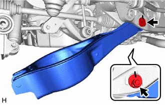
- Engage the 2 guides to install the rear suspension arm cover.
- Install the rear suspension arm cover to the rear No. 2 suspension arm assembly with the 2 bolts.
Torque: 12 N.m (122 kgf/cm, 9 ft.lbf)
- INSTALL TAIL EXHAUST PIPE ASSEMBLY (for RH Side)
for A25A-FXS: Refer to INSTALLATION [12/2019 - 10/2022]
for 2GR-FKS: Refer to INSTALLATION [12/2019 - 10/2022]
- INSTALL REAR WHEEL
Refer to PROCEDURE - Step 1
- INSTALL REAR NO. 2 SUSPENSION ARM ASSEMBLY
- Lower the vehicle to the ground.
- Bounce the vehicle up and down at the corners to stabilize the rear suspension.
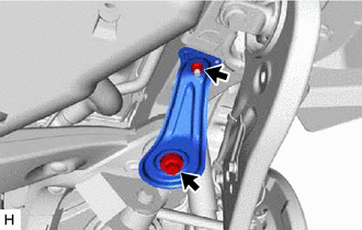
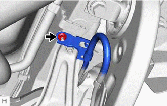
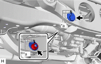
- Align the matchmarks on the rear No. 2 suspension camber adjust cam, rear suspension toe adjust cam sub-assembly and rear suspension member sub-assembly.
*a Matchmark - Fully tighten the nut.
Torque: 100 N.m (1020 kgf/cm, 74 ft.lbf)
NOTE:- Hold the rear suspension toe adjust cam sub-assembly while rotating the nut.
- Make sure that the vehicle is unloaded when fully tightening the nut.
- INSPECT AND ADJUST REAR WHEEL ALIGNMENT
Refer to ADJUSTMENT [12/2019 - 09/2020] , or refer to ADJUSTMENT [09/2020 - 10/2022]
- INSPECT FOR EXHAUST GAS LEAK (for RH Side)
for A25A-FXS: Refer to PROCEDURE - Step 6
for 2GR-FKS: Refer to PROCEDURE - Step 6
- PERFORM INITIALIZATION
Parking Assist Monitor System Refer to CALIBRATION [12/2019 - 10/2022] Panoramic View Monitor System Refer to CALIBRATION [12/2019 - 10/2022] Lighting System (EXT) (w/ AFS) Refer to INITIALIZATION [12/2019 - 11/2023]