Image from Camera for Panoramic View Monitor is Abnormal [10/2022 - ]: Procedure
- CHECK PANORAMIC VIEW MONITOR SYSTEM
- Check if the same malfunction occurs when the panoramic view monitor screen is displayed.
Result
Result Proceed to Rear view screen is not displayed. A Front view screen is not displayed. B Side monitor screen (LH side) is not displayed. C Side monitor screen (RH side) is not displayed. D Panoramic view monitor screen is not displayed. E Multiple camera images are not displayed or are distorted. F
Result:
B
See step 5
Result:
C
See step 8
Result:
D
See step 13
Result:
E
See step 18
Result:
F
See step 21
Result:
A
See step 2
- Check if the same malfunction occurs when the panoramic view monitor screen is displayed.
- CHECK HARNESS AND CONNECTOR (PARKING ASSIST ECU - REAR TELEVISION CAMERA ASSEMBLY)
- Disconnect the H125 parking assist ECU connector.
- Disconnect the W31 rear television camera assembly connector.
- Measure the resistance according to the value(s) in the table below.
Standard Resistance
Tester Connection Condition Specified Condition H125-1 (CB+) - W31-2 (CB+) Always Below 1 Ω H125-3 (CV+) - W31-4 (CV+) Always Below 1 Ω H125-4 (CV-) - W31-3 (CV-) Always Below 1 Ω H125-2 (CGND) - W31-1 (CGND) Always Below 1 Ω H125-5 (SGND) - W31-5 (SGND) Always Below 1 Ω H125-1 (CB+) or W31-2 (CB+) - Body ground Always 10 kΩ or higher H125-3 (CV+) or W31-4 (CV+) - Body ground Always 10 kΩ or higher H125-4 (CV-) or W31-3 (CV-) - Body ground Always 10 kΩ or higher H125-2 (CGND) or W31-1 (CGND) - Body ground Always 10 kΩ or higher H125-5 (SGND) - W31-5 (SGND) - Body ground Always 10 kΩ or higher Result
Proceed to OK NG
Result:
NG
REPAIR OR REPLACE HARNESS OR CONNECTOR
Result:
OK
See step 3
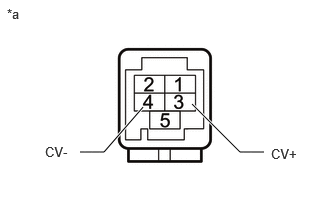
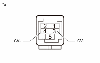
- CHECK PARKING ASSIST ECU (CV+, CV-)
- Disconnect the H125 parking assist ECU connector.
*a Component without harness connected
(Parking Assist ECU) - Measure the resistance according to the value(s) in the table below.
Standard Resistance
Tester Connection Condition Specified Condition 3 (CV+) - Body ground Always 10 kΩ or higher 4 (CV-) - Body ground Always 10 kΩ or higher Result
Proceed to OK NG
Result:
NG
REPLACE PARKING ASSIST ECU
Refer to REMOVAL [10/2022 - 11/2023] , or refer to REMOVAL [11/2023 - ]
Result:
OK
See step 4
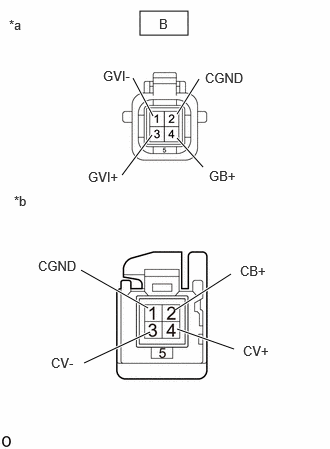
- Disconnect the H125 parking assist ECU connector.
- CHECK PARKING ASSIST ECU (CB+, CGND)
- Disconnect the rear television camera assembly.
- Measure the resistance according to the value(s) in the table below.
Standard Resistance
Tester Connection Condition Specified Condition W31-1 (CGND) - Body ground Always Below 1 Ω - Measure the voltage according to the value(s) in the table below.
Standard Voltage
Tester Connection Switch Condition Specified Condition W31-2 (CB+) - W31-1 (CGND) Ignition switch ON 7.5 to 8.5 V Result
Proceed to OK NG
Result:
OK
REPLACE REAR TELEVISION CAMERA ASSEMBLY
Refer to REMOVAL [12/2019 - 11/2023] , or refer to REMOVAL [11/2023 - ]
Result:
NG
REPLACE PARKING ASSIST ECU
Refer to REMOVAL [10/2022 - 11/2023] , or refer to REMOVAL [11/2023 - ]
- CHECK HARNESS AND CONNECTOR (PARKING ASSIST ECU - FRONT TELEVISION CAMERA ASSEMBLY)
- Disconnect the H127 parking assist ECU connector.
- Disconnect the B9 front television camera assembly connector.
- Measure the resistance according to the value(s) in the table below.
Standard Resistance
Tester Connection Condition Specified Condition H127-1 (CB+) - B9-2 (CB+) Always Below 1 Ω H127-3 (CV+) - B9-4 (CV+) Always Below 1 Ω H127-4 (CV-) - B9-3 (CV-) Always Below 1 Ω H127-2 (CGND) - B9-1 (CGND) Always Below 1 Ω H127-5 (SGND) - B9-5 (SGND) Always Below 1 Ω H127-1 (CB+) or B9-2 (CB+) - Body ground Always 10 kΩ or higher H127-3 (CV+) or B9-4 (CV+) - Body ground Always 10 kΩ or higher H127-4 (CV-) or B9-3 (CV-) - Body ground Always 10 kΩ or higher H127-2 (CGND) or B9-1 (CGND) - Body ground Always 10 kΩ or higher H127-5 (SGND) or B9-5 (SGND) - Body ground Always 10 kΩ or higher Result
Proceed to OK NG
Result:
NG
REPAIR OR REPLACE HARNESS OR CONNECTOR
Result:
OK
See step 6
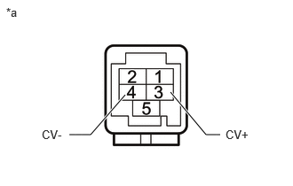
- CHECK PARKING ASSIST ECU (CV+, CV-)
- Disconnect the H127 parking assist ECU connector.
*a Component without harness connected
(Parking Assist ECU) - Measure the resistance according to the value(s) in the table below.
Standard Resistance
Tester Connection Condition Specified Condition 3 (CV+) - Body ground Always 10 kΩ or higher 4 (CV-) - Body ground Always 10 kΩ or higher Result
Proceed to OK NG
Result:
NG
REPLACE PARKING ASSIST ECU
Refer to REMOVAL [10/2022 - 11/2023] , or refer to REMOVAL [11/2023 - ]
Result:
OK
See step 7
- Disconnect the H127 parking assist ECU connector.
- CHECK PARKING ASSIST ECU (CB+, CGND)
- Disconnect the front television camera assembly connector.
- Measure the resistance according to the value(s) in the table below.
Standard Resistance
Tester Connection Condition Specified Condition B9-1 (CGND) - Body ground Always Below 1 Ω - Measure the voltage according to the value(s) in the table below.
Standard Voltage
Tester Connection Switch Condition Specified Condition B9-2 (CB+) - B9-1 (CGND) Ignition switch ON 7.5 to 8.5 V Result
Proceed to OK NG
Result:
OK
REPLACE FRONT TELEVISION CAMERA ASSEMBLY
Refer to REMOVAL [12/2019 - 11/2023] , or refer to REMOVAL [11/2023 - ]
Result:
NG
REPLACE PARKING ASSIST ECU
Refer to REMOVAL [10/2022 - 11/2023] , or refer to REMOVAL [11/2023 - ]
- CHECK HARNESS AND CONNECTOR (PARKING ASSIST ECU - OUTER REAR VIEW MIRROR ASSEMBLY LH)
- Disconnect the H128 parking assist ECU connector.
- Disconnect the J34 outer rear view mirror assembly LH connector.
- Measure the resistance according to the value(s) in the table below.
Standard Resistance
Tester Connection Condition Specified Condition H128-1 (CB+) - J34-2 (CB+) Always Below 1 Ω H128-3 (CV+) - J34-4 (CV+) Always Below 1 Ω H128-4 (CV-) - J34-3 (CV-) Always Below 1 Ω H128-2 (CGND) - J34-1 (CGND) Always Below 1 Ω H128-5 (SGND) - J34-5 (SGND) Always Below 1 Ω H128-1 (CB+) or J34-2 (CB+) - Body ground Always 10 kΩ or higher H128-3 (CV+) or J34-4 (CV+) - Body ground Always 10 kΩ or higher H128-4 (CV-) or J34-3 (CV-) - Body ground Always 10 kΩ or higher H128-2 (CGND) or J34-1 (CGND) - Body ground Always 10 kΩ or higher H128-5 (SGND) or J34-5 (SGND) - Body ground Always 10 kΩ or higher Result
Proceed to OK NG
Result:
NG
REPAIR OR REPLACE HARNESS OR CONNECTOR
Result:
OK
See step 9
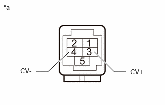
- CHECK PARKING ASSIST ECU (CV+, CV-)
- Disconnect the H128 parking assist ECU connector.
*a Component without harness connected
(Parking Assist ECU) - Measure the resistance according to the value(s) in the table below.
Standard Resistance
Tester Connection Condition Specified Condition 3 (CV+) - Body ground Always 10 kΩ or higher 4 (CV-) - Body ground Always 10 kΩ or higher Result
Proceed to OK NG
Result:
NG
REPLACE PARKING ASSIST ECU
Refer to REMOVAL [10/2022 - 11/2023] , or refer to REMOVAL [11/2023 - ]
Result:
OK
See step 10
- Disconnect the H128 parking assist ECU connector.
- CHECK PARKING ASSIST ECU (CB+, CGND)
- Disconnect the outer rear view mirror assembly LH connector.
- Measure the resistance according to the value(s) in the table below.
Standard Resistance
Tester Connection Condition Specified Condition J34-1 (CGND) - Body ground Always Below 1 Ω - Measure the voltage according to the value(s) in the table below.
Standard Voltage
Tester Connection Switch Condition Specified Condition J34-2 (CB+) - J34-1 (CGND) Ignition switch ON 7.5 to 8.5 V Result
Proceed to OK NG
Result:
NG
REPLACE PARKING ASSIST ECU
Refer to REMOVAL [10/2022 - 11/2023] , or refer to REMOVAL [11/2023 - ]
Result:
OK
See step 11
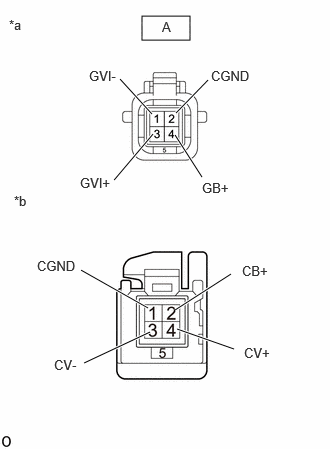
- INSPECT OUTER REAR VIEW MIRROR ASSEMBLY LH
- Disconnect the outer rear view mirror assembly LH connector.
*a Front view of wire harness connector
(to Side Television Camera Assembly LH)*b Component without harness connected
(Outer Rear View Mirror Assembly LH) - Disconnect the side television camera assembly LH connector.
- Measure the resistance according to the value(s) in the table below.
Standard Resistance
Tester Connection Condition Specified Condition 2 (CB+) - A-4 (GB+) Always Below 1 Ω 4 (CV+) - A-3 (GVI+) Always Below 1 Ω 3 (CV-) - A-1 (GVI-) Always Below 1 Ω 1 (CGND) - A-2 (CGND) Always Below 1 Ω 2 (CB+) or A-4 (GB+) - Body ground Always 10 kΩ or higher 4 (CV+) or A-3 (GVI+) - Body ground Always 10 kΩ or higher 3 (CV-) or A-1 (GVI-) - Body ground Always 10 kΩ or higher 1 (CGND) or A-2 (CGND) - Body ground Always 10 kΩ or higher Result
Proceed to OK NG
Result:
NG
REPLACE OUTER REAR VIEW MIRROR ASSEMBLY LH
Refer to REMOVAL [12/2019 - 11/2023] , or refer to REMOVAL [11/2023 - ]
Result:
OK
See step 12
- Disconnect the outer rear view mirror assembly LH connector.
- CHECK SIDE TELEVISION CAMERA ASSEMBLY LH
- Replace the side television camera assembly LH with a new or normally functioning one.
Refer to REMOVAL [10/2022 - 11/2023] , or refer to REMOVAL [11/2023 - ]
- Check if the same malfunction reoccurs when the side monitor screen is displayed.
Result
Proceed to OK NG
Result:
OK
END (SIDE TELEVISION CAMERA ASSEMBLY LH WAS DEFECTIVE)
Result:
NG
REPLACE PARKING ASSIST ECU
Refer to REMOVAL [10/2022 - 11/2023] , or refer to REMOVAL [11/2023 - ]
- Replace the side television camera assembly LH with a new or normally functioning one.
- CHECK HARNESS AND CONNECTOR (PARKING ASSIST ECU - OUTER REAR VIEW MIRROR ASSEMBLY RH)
- Disconnect the H126 parking assist ECU connector.
- Disconnect the J33 outer rear view mirror assembly RH connector.
- Measure the resistance according to the value(s) in the table below.
Standard Resistance
Tester Connection Condition Specified Condition H126-1 (CB+) - J33-2 (CB+) Always Below 1 Ω H126-3 (CV+) - J33-4 (CV+) Always Below 1 Ω H126-4 (CV-) - J33-3 (CV-) Always Below 1 Ω H126-2 (CGND) - J33-1 (CGND) Always Below 1 Ω H126-5 (SGND) - J33-5 (SGND) Always Below 1 Ω H126-1 (CB+) or J33-2 (CB+) - Body ground Always 10 kΩ or higher H126-3 (CV+) or J33-4 (CV+) - Body ground Always 10 kΩ or higher H126-4 (CV-) or J33-3 (CV-) - Body ground Always 10 kΩ or higher H126-2 (CGND) or J33-1 (CGND) - Body ground Always 10 kΩ or higher H126-5 (SGND) or J33-5 (SGND) - Body ground Always 10 kΩ or higher Result
Proceed to OK NG
Result:
NG
REPAIR OR REPLACE HARNESS OR CONNECTOR
Result:
OK
See step 14
- CHECK PARKING ASSIST ECU (CV+, CV-)
- Disconnect the H126 parking assist ECU connector.
*a Component without harness connected
(Parking Assist ECU) - Measure the resistance according to the value(s) in the table below.
Standard Resistance
Tester Connection Condition Specified Condition 3 (CV+) - Body ground Always 10 kΩ or higher 4 (CV-) - Body ground Always 10 kΩ or higher Result
Proceed to OK NG
Result:
NG
REPLACE PARKING ASSIST ECU
Refer to REMOVAL [10/2022 - 11/2023] , or refer to REMOVAL [11/2023 - ]
Result:
OK
See step 15
- Disconnect the H126 parking assist ECU connector.
- CHECK PARKING ASSIST ECU (CB+, CGND)
- Disconnect the outer rear view mirror assembly RH connector.
- Measure the resistance according to the value(s) in the table below.
Standard Resistance
Tester Connection Condition Specified Condition J33-1 (CGND) - Body ground Always Below 1 Ω - Measure the voltage according to the value(s) in the table below.
Standard Voltage
Tester Connection Switch Condition Specified Condition J33-2 (CB+) - J33-1 (CGND) Ignition switch ON 7.5 to 8.5 V Result
Proceed to OK NG
Result:
NG
REPLACE PARKING ASSIST ECU
Refer to REMOVAL [10/2022 - 11/2023] , or refer to REMOVAL [11/2023 - ]
Result:
OK
See step 16
- INSPECT OUTER REAR VIEW MIRROR ASSEMBLY RH
- Disconnect the side television camera assembly RH connector.
*a Front view of wire harness connector
(to Side Television Camera Assembly RH)*b Component without harness connected
(Outer Rear View Mirror Assembly RH) - Disconnect the outer rear view mirror assembly RH connector.
- Measure the resistance according to the value(s) in the table below.
Standard Resistance
Tester Connection Condition Specified Condition 2 (CB+) - B-4 (GB+) Always Below 1 Ω 4 (CV+) - B-3 (GVI+) Always Below 1 Ω 3 (CV-) - B-1 (GVI-) Always Below 1 Ω 1 (CGND) - B-2 (CGND) Always Below 1 Ω 2 (CB+) or B-4 (GB+) - Body ground Always 10 kΩ or higher 4 (CV+) or B-3 (GVI+) - Body ground Always 10 kΩ or higher 3 (CV-) or B-1 (GVI-) - Body ground Always 10 kΩ or higher 1 (CGND) or B-2 (CGND) - Body ground Always 10 kΩ or higher Result
Proceed to OK NG
Result:
NG
REPLACE OUTER REAR VIEW MIRROR ASSEMBLY RH
Refer to REMOVAL [12/2019 - 11/2023] , or refer to REMOVAL [11/2023 - ]
Result:
OK
See step 17
- Disconnect the side television camera assembly RH connector.
- CHECK SIDE TELEVISION CAMERA ASSEMBLY RH
- Replace the side television camera assembly RH with a new or normally functioning one.
Refer to REMOVAL [10/2022 - 11/2023] , or refer to REMOVAL [11/2023 - ]
- Check if the same malfunction reoccurs when the side monitor screen is displayed.
Result
Proceed to OK NG
Result:
OK
END (SIDE TELEVISION CAMERA ASSEMBLY RH WAS DEFECTIVE)
Result:
NG
REPLACE PARKING ASSIST ECU
Refer to REMOVAL [10/2022 - 11/2023] , or refer to REMOVAL [11/2023 - ]
- Replace the side television camera assembly RH with a new or normally functioning one.
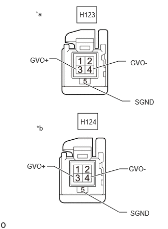
- CHECK GVIF CABLE (Digital video signal line)
*a Front side of GVIF signal line connector
(to parking assist ECU)*b Front side of GVIF signal line connector
(to radio and display receiver assembly)- Disconnect the H123 parking assist ECU connector.
- Disconnect the H124 radio and display receiver assembly connector.
- Measure the resistance according to the value(s) in the table below.
Standard Resistance
Tester Connection Condition Specified Condition H123-3 (GVO+) - H124-3 (GVO+) Always Below 1 Ω H123-4 (GVO-) - H124-4 (GVO-) Always Below 1 Ω H123-5 (SGND) - H124-5 (SGND) Always Below 1 Ω H123-3 (GVO+) or H124-3 (GVO+) - Body ground Always 10 kΩ or higher H123-4 (GVO-) or H124-4 (GVO-) - Body ground Always 10 kΩ or higher H123-5 (SGND) or H124-5 (SGND) - Body ground Always 10 kΩ or higher Result
Proceed to OK NG
Result:
NG
REPLACE GVIF CABLE (DIGITAL VIDEO SIGNAL LINE)
Result:
OK
See step 19
- REPLACE WIRE HARNESS (PARKING ASSIST ECU - INE BETWEEN RADIO AND DISPLAY RECEIVER ASSEMBLY)
- Replace the GVIF signal line with a new or known good one.
- Check if the same malfunction reoccurs when the panoramic view monitor screen is displayed.
Refer to "CHK" message(s) are displayed on the SIGNAL CHECK screen. [10/2022 - ]
Result
Result Proceed to Display normally A Abnormality reproduces B HINT:
If the panoramic view monitor screen is displayed normally after exchanging the GVIF signal line between the parking assist computer and the radio and display receiver assembly, it can be determined that the GVIF signal line between the parking assist computer and the radio and display receiver assembly is defective.
Result:
A
END (DEFECTIVE GVIF SIGNAL LINE)
Result:
B
See step 20
- CHECK RADIO AND DISPLAY RECEIVER ASSEMBLY
- Replace the radio and display receiver assembly with a new or known good one.
Refer to REMOVAL [10/2022 - 11/2023] , or refer to REMOVAL [11/2023 - ]
- Check if the same malfunction reoccurs when the panoramic view monitor screen is displayed.
Result
Result Proceed to Display normally A Abnormality reproduces B
Result:
A
RADIO AND DISPLAY RECEIVER ASSEMBLY (RADIO AND DISPLAY RECEIVER ASSEMBLY DEFECTIVE)
Result:
B
REPLACE PARKING ASSIST ECU
Refer to REMOVAL [10/2022 - 11/2023] , or refer to REMOVAL [11/2023 - ]
- Replace the radio and display receiver assembly with a new or known good one.
- CAMERA IMAGE CHECK
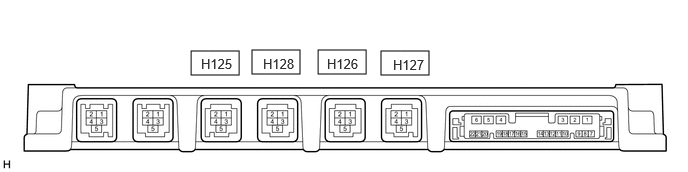
- One by one in order, repeatedly disconnect then reconnect the H125, H128, H126 and H127 parking assist ECU connector. When disconnected, check the camera image for a black screen or distortion.
Result
Result Proceed to When connector H125 is disconnected, only the rear camera image is black or distorte A When connector H127 is disconnected, only the front camera image is black or distorted B When connector H128 is disconnected, only the left-side camera image is black or distorted C When connector H126 is disconnected, only the right-side camera image is black or distorted D Other than above E
Result:
A
See step 2
Result:
B
See step 5
Result:
C
See step 8
Result:
D
See step 13
Result:
E
REPLACE PARKING ASSIST ECU
Refer to REMOVAL [10/2022 - 11/2023] , or refer to REMOVAL [11/2023 - ]
- One by one in order, repeatedly disconnect then reconnect the H125, H128, H126 and H127 parking assist ECU connector. When disconnected, check the camera image for a black screen or distortion.