DTC C1622: Open or Short Circuit in Back Camera Signal [12/2019 - 10/2022]: Procedure
- CHECK HARNESS AND CONNECTOR (PARKING ASSIST ECU - REAR TELEVISION CAMERA ASSEMBLY)
- Disconnect the H19 parking assist ECU connector.
- Disconnect the W15 rear television camera assembly connector.
- Measure the resistance according to the value(s) in the table below.
Standard Resistance
Tester Connection Condition Specified Condition H19-33 (CB+) - W15-6 (CB+) Always Below 1 Ω H19-29 (CV+) - W15-3 (CV+) Always Below 1 Ω H19-30 (CV-) - W15-2 (CV-) Always Below 1 Ω H19-32 (CGND) - W15-5 (CGND) Always Below 1 Ω H19-33 (CB+) or W15-6 (CB+) - Body ground Always 10 kΩ or higher H19-29 (CV+) or W15-3 (CV+) - Body ground Always 10 kΩ or higher H19-30 (CV-) or W15-2 (CV-) - Body ground Always 10 kΩ or higher H19-32 (CGND) or W15-5 (CGND) - Body ground Always 10 kΩ or higher H19-31 (SGND) - Body ground Always 10 kΩ or higher Result
Proceed to OK NG
Result:
NG
REPAIR OR REPLACE HARNESS OR CONNECTOR
Result:
OK
See step 2
- CHECK PARKING ASSIST ECU (CV-, CGND)
- Disconnect the H19 parking assist ECU connector.
- Measure the resistance according to the value(s) in the table below.
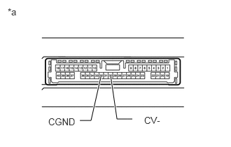
*a Component without harness connected
(Parking Assist ECU)Standard Resistance
Tester Connection Condition Specified Condition 30 (CV-) - Body ground Always Below 1 Ω 32 (CGND) - Body ground Always Below 1 Ω Result
Proceed to OK NG
Result:
NG
REPLACE PARKING ASSIST ECU. Refer to REMOVAL [12/2019 - 10/2022]
Result:
OK
See step 3
- CHECK PARKING ASSIST ECU (CB+, CGND)
- Measure the resistance according to the value(s) in the table below.
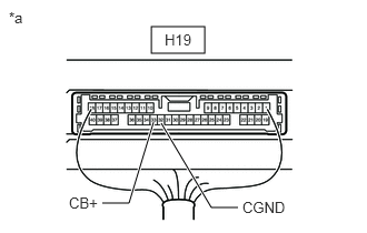
*a Component with harness connected
(Parking Assist ECU)Standard Resistance
Tester Connection Condition Specified Condition H19-32 (CGND) - Body ground Always Below 1 Ω - Measure the voltage according to the value(s) in the table below.
Standard Voltage
Tester Connection Switch Condition Specified Condition H19-33 (CB+) - H19-32 (CGND) Ignition switch ON 5.5 to 7.05 V H19-33 (CB+) - H19-32 (CGND) Ignition switch off Below 1 V Result
Proceed to OK NG
Result:
NG
REPLACE PARKING ASSIST ECU. Refer to REMOVAL [12/2019 - 10/2022]
Result:
OK
See step 4
- Measure the resistance according to the value(s) in the table below.
- CHECK REAR TELEVISION CAMERA ASSEMBLY (CV+, CGND)
- Remove the parking assist ECU with the connector still connected.
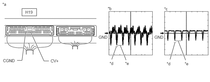
- Using an oscilloscope, check the waveform of the rear television camera assembly.
HINT:
A waterproof connector is used for the rear television camera assembly. Therefore, inspect the waveform at the parking assist ECU with the connector connected.
*a Component with harness connected
(Parking Assist ECU)*b Waveform 1 (camera lens not covered, displaying an image) *c Waveform 2 (camera lens covered, blacking out the screen) *d Synchronization Signal *e Video Waveform - - HINT:
- The video waveform changes according to the image sent by the rear television camera assembly.
- The video waveform is constantly output when the ignition switch is turned to ACC.
MEASUREMENT CONDITIONItem Content Terminal No. (Symbol) H19-29 (CV+) - H19-32 (CGND) Tool Setting 200 mV/DIV., 50 μsec./DIV. Condition Ignition switch ON, panoramic view monitor system operating OK
Waveform is similar to that shown in the illustration.
Result
Proceed to OK NG
Result:
OK
REPLACE PARKING ASSIST ECU. Refer to REMOVAL [12/2019 - 10/2022]
Result:
NG
REPLACE REAR TELEVISION CAMERA ASSEMBLY. Refer to REMOVAL [12/2019 - 11/2023]