Inspection [12/2019 - ]: Procedure
- INSPECT FUEL LID LOCK WITH MOTOR ASSEMBLY
- Check the operation of the fuel lid lock with motor assembly (motor operation).
- Apply auxiliary battery voltage to the fuel lid lock with motor assembly connector, and check the operation of the fuel lid lock with motor assembly.
Standard
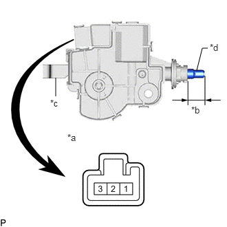
Auxiliary Battery Connection Specified Condition Auxiliary battery positive (+) → Terminal 1
Auxiliary battery negative (-) → Terminal 215.45 to 16.65 mm
(0.608 to 0.656 in.)If the result is not as specified, replace the fuel lid lock with motor assembly.
*a Component without harness connected
(Fuel Lid Lock with Motor Assembly)*b Shaft Stroke *c Lever *d Shaft
- Apply auxiliary battery voltage to the fuel lid lock with motor assembly connector, and check the operation of the fuel lid lock with motor assembly.
- Check the operation of the fuel lid lock with motor assembly (fuel lid courtesy switch).
- Measure the shaft stroke.
Standard
Area Condition Specified Condition Shaft stroke Lever pulled 15.45 to 16.65 mm
(0.608 to 0.656 in.)If the result is not as specified, replace the fuel lid lock with motor assembly.
- Check the operation of the fuel lid lock with motor assembly (motor operation).