Inspection [11/2024 - ]: Procedure
- INSPECT NAVIGATION ANTENNA ASSEMBLY (w/o Manual (SOS) Switch)
- Check that the navigation antenna assembly cable is properly installed and does not have any sharp bends, pinching or loose connections.
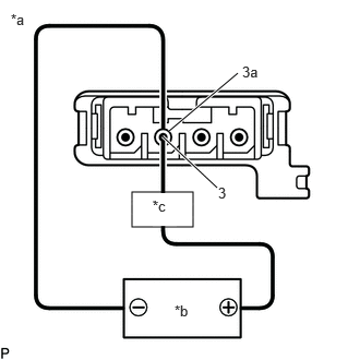
*a Component without harness connected
(Navigation Antenna Assembly)*b Voltage Applied between Terminals *c Electrical Tester Current consumption check:
- As shown in the illustration, connect the power supply and the electrical tester, and measure the current consumption according to the value(s) in the table below.
Standard Current
Condition Specified Condition 4.2 to 5 V applied between terminals 3 (core) and 3a (shield) 10 to 30 mA NOTE:Do not apply 6 V or more between terminals 3 and 3a.
HINT:
If a stable power supply is not available, connect 4 nickel-metal hydride batteries (1.2 V each) or equivalent in series.
- As shown in the illustration, connect the power supply and the electrical tester, and measure the current consumption according to the value(s) in the table below.
- INSPECT NAVIGATION ANTENNA ASSEMBLY (w/ Manual (SOS) Switch)
- Check that the navigation antenna assembly cable is properly installed and does not have any sharp bends, pinching or loose connections.
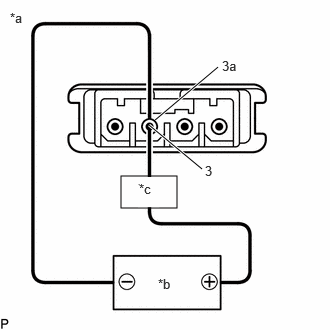
*a Component without harness connected
(Navigation Antenna Assembly)*b Voltage Applied between Terminals *c Electrical Tester Current consumption check: (GNSS1)
- As shown in the illustration, connect the power supply and the electrical tester, and measure the current consumption according to the value(s) in the table below.
Standard Current
Condition Specified Condition 4.2 to 5 V applied between terminals 3 (core) and 3a (shield) 10 to 30 mA NOTE:Do not apply 6 V or more between terminals 3 and 3a.
HINT:
If a stable power supply is not available, connect 4 nickel-metal hydride batteries (1.2 V each) or equivalent in series.
- As shown in the illustration, connect the power supply and the electrical tester, and measure the current consumption according to the value(s) in the table below.
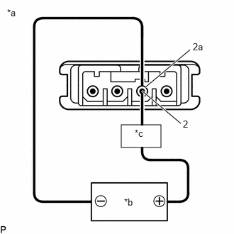
*a Component without harness connected
(Navigation Antenna Assembly)*b Voltage Applied between Terminals *c Electrical Tester Current consumption check: (GNSS2)
- As shown in the illustration, connect the power supply and the electrical tester, and measure the current consumption according to the value(s) in the table below.
Standard Current
Condition Specified Condition 4.2 to 5 V applied between terminals 2 (core) and 2a (shield) 10 to 30 mA NOTE:Do not apply 6 V or more between terminals 2 and 2a.
HINT:
If a stable power supply is not available, connect 4 nickel-metal hydride batteries (1.2 V each) or equivalent in series.
- As shown in the illustration, connect the power supply and the electrical tester, and measure the current consumption according to the value(s) in the table below.
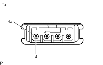
- Resistance check: (Telephone Sub)
*a Component without harness connected
(Navigation Antenna Assembly)