Terminals Of Ecu [12/2019 - 10/2022]
HINT:
Check from the rear of the connector while it is connected to the components.
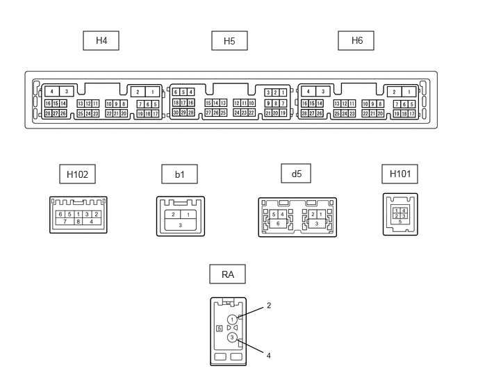
- RADIO RECEIVER ASSEMBLY
Terminal No. (Symbol) Terminal Description Condition Specified Condition H4-1 (GND1) - Body ground Ground Always Below 1 Ω H4-4 (+B1) - H4-1 (GND1) Power source (+B) Ignition switch off*3
Always*411 to 14 V*5
10.5 to 16 V*6H4-15 (ACC1) - H4-1 (GND1) Power source (ACC) Ignition switch off Below 1 V Ignition switch ACC 11 to 14 V*5
10.5 to 16 V*6H4-19 (TX+)*2 AVC-LAN communication signal - - H4-20 (TX-)*2 AVC-LAN communication signal - - H4-21 (SW1) - H4-24 (SWG) Steering pad switch signal No switch pushed 2.97 to 3.56 V Seek+ switch pushed 0.27 to 0.35 V Seek- switch pushed 0.86 to 1.03 V Volume+ switch pushed 1.51 to 1.79 V Volume- switch pushed 2.22 to 2.66 V H4-22 (SW2) - H4-24 (SWG) Steering pad switch signal No switch pushed 2.97 to 3.56 V MODE switch pushed 0.27 to 0.35 V On/off hook switch pushed 1.51 to 1.79 V Voice switch pushed 2.22 to 2.66 V H4-24 (SWG) - Body ground Steering pad switch signal Always Below 1 Ω H4-27 (SPD) - H4-1 (GND1) Vehicle speed signal See "Vehicle Signal Check Mode" in Operation Check
Refer to OPERATION CHECK [12/2019 - 10/2022]- H4-28 (REV) - H4-1 (GND1) Reverse signal See "Check Vehicle Signal" in Operation Check
Refer to OPERATION CHECK [12/2019 - 10/2022]- H5-1 (VMTF) - H4-1 (GND1) Visual mute signal Ignition switch ACC Screen display changing 3.5 V or higher → Below 1 V → 3.5 V or higher H5-5 (CNH1) Local bus communication signal - - H5-6 (CNL1) Local bus communication signal - - H5-13 (CANH) CAN communication signal - - H5-14 (CANL) CAN communication signal - - H5-15 (ILL+) - H4-1 (GND1) Illumination signal Light control switch off Below 1 V Ignition switch off
Light control switch in tail or head position11 to 14 V H5-16 (ILL-) - H4-1 (GND1) Illumination signal Light control switch off Below 1 V Light control switch in tail or head position Pulse generation H5-19 (IG) - H4-1 (GND1) Power source (IG) Ignition switch off Below 1 V Ignition switch ON 11 to 14 V H5-20 (PKB) - H4-1 (GND1) Parking brake signal See "Check Vehicle Signal" in Operation Check
Refer to OPERATION CHECK [12/2019 - 10/2022]- H5-21 (MIN+) - H4-1 (GND1) Microphone voice signal See "Microphone Check" in Operation Check
Refer to OPERATION CHECK [12/2019 - 10/2022]- H5-22 (MIN-) - Body ground Microphone voice signal See "Microphone Check" in Operation Check
Refer to OPERATION CHECK [12/2019 - 10/2022]- H5-24 (SGND) - Body ground Shield ground Always Below 1 Ω H5-25 (SNS2) - H4-1 (GND1) Microphone connection detection signal Always Below 1 V H101-1 (USV1) Power source - - H101-2 (US1-) Data signal - - H101-3 (US1+) Data signal - - H101-4 (UGD1) Ground - - H101-5 (USG1) - Body ground Shield ground Always Below 1 Ω b1-1 (GV+) Video signal (Digital) - - b1-2 (GV-) Video signal (Digital) - - b1-3 (GVG) - Body ground Shield ground Always Below 1 Ω d5-1 (GV2-) Video signal (Digital) - - d5-2 (GV2+) Video signal (Digital) - - d5-3 (GVG2) - Body ground Shield ground Always Below 1 Ω d5-4 (US4+) USB communication line - - d5-5 (US4-) USB communication line - - d5-6 (UGD4) - Body ground Shield ground Always Below 1 Ω H102-1 (WUO) MOST communication wake-up signal - - H102-2 (MI+) MOST communication signal - - H102-3 (MI-) MOST communication signal - - H102-4 (SLDI) Shield ground - - H102-5 (MO+) MOST communication signal - - H102-6 (MO-) MOST communication signal - - H102-7 (SLDO) Shield ground - - H6-7 (SUP) - H4-1 (GND1) Start up signal 20 seconds elapse after turning the ignition switch ACC 11 to 14 V H6-10 (USBV) - H4-1 (GND1) DCM (telematics transceiver) power supply Ignition switch off Below 1 V Ignition switch ACC 4.75 to 5.25 V H6-11 (USBG) - Body ground Ground Always Below 1 Ω H6-17 (TX4+) AVC-LAN communication signal - - H6-18 (TX4-) AVC-LAN communication signal - - H6-19 (RST)*1 - - - H6-22 (SI+) - H4-1 (GND1) Voice signal Voice guidance sounding A waveform synchronized with sound is output H6-23 (SI-) - H4-1 (GND1) Voice signal Voice guidance sounding A waveform synchronized with sound is output H6-24 (SGND) - H4-1 (GND1) Shield ground Always Below 1 Ω H6-25 (MCO+) - H6-26 (MCO-) Microphone voice signal See "Check Microphone (DCU)" in Operation Check
Refer to OPERATION CHECK [12/2019 - 10/2022]- H6-26 (MCO-) - H4-1 (GND1) Microphone voice signal See "Check Microphone (DCU)" in Operation Check
Refer to OPERATION CHECK [12/2019 - 10/2022]- H6-28 (REV2) - H4-1 (GND1) Reverse signal Hybrid system operating, shift lever not in R → in R*3
Engine running, shift lever not in R → in R*42 V or less → 11 to 14 V RA-5 (ANT+) - H4-1 (GND1) Power source of antenna Ignition switch ACC
Radio switch on and AM or FM selected11 to 14 V - *1: Terminal exists but is not used
- *2: w/ Rear Seat Entertainment System
- *3: for HV Model
- *4: for Gasoline Model
- *5: w/o Stop and Start System
- *6: w/ Stop and Start System
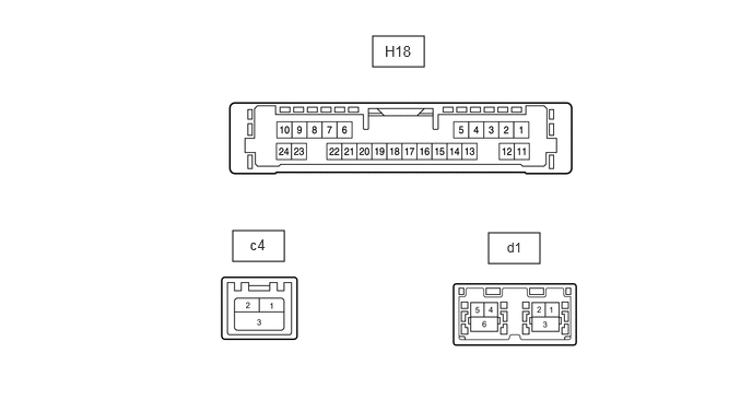
- NAVIGATION ECU
Terminal No. (Symbol) Terminal Description Condition Specified Condition H18-6 (VOI+) - H18-23 (GND) Voice signal Voice guidance sounding A waveform synchronized with sound is output H18-7 (VOI-) - H18-23 (GND) Voice signal Voice guidance sounding A waveform synchronized with sound is output H18-8 (SLD1) - Body ground Shield ground Always Below 1 Ω H18-9 (SPD) - H18-23 (GND) Vehicle speed signal See "Check GPS and Vehicle Sensors" in Operation Check
Refer to OPERATION CHECK [12/2019 - 10/2022]- H18-10 (+B) - H18-23 (GND) Power source (+B) Ignition switch off*2
Always*311 to 14 V*4
10.5 to 16 V*5H18-13 (MIC+) - H18-23 (GND) Microphone voice signal See "Microphone Check (MEU)" in Operation Check
Refer to OPERATION CHECK [12/2019 - 10/2022]- H18-14 (MIC-) - Body ground Microphone voice signal See "Microphone Check (MEU)" in Operation Check
Refer to OPERATION CHECK [12/2019 - 10/2022]- H18-19 (REV2) - H18-23 (GND) Reverse signal Hybrid system operating, shift lever not in R → in R*2
Engine running, shift lever not in R → in R*32 V or less → 11 to 14 V H18-21 (SUP) - H18-23 (GND) Power source (ACC) 20 seconds elapse after turning the ignition switch to ACC 11 to 14 V H18-22 (RST)*1 - - - H18-23 (GND) - Body ground Ground Always Below 1 Ω c4-1 (USB+) USB communication line - - c4-2 (USB-) USB communication line - - c4-3 (USBS) - Body ground Shield ground Always Below 1 Ω d1-1 (GVO-) Video signal (Digital) - - d1-2 (GVO+) Video signal (Digital) - - d1-3 (GVG1) - Body ground Shield ground Always Below 1 Ω d1-4 (US4+) USB communication line - - d1-5 (US4-) USB communication line - - d1-6 (UGD4) - Body ground Shield ground Always Below 1 Ω - *1: Terminal exists but is not used
- *2: for HV Model
- *3: for Gasoline Model
- *4: w/o Stop and Start System
- *5: w/ Stop and Start System
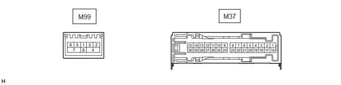
- STEREO COMPONENT AMPLIFIER ASSEMBLY
Terminal No. (Symbol) Terminal Description Condition Specified Condition M37-1 (+B) - M37-3 (GND) Power source (+B) Ignition switch off*1
Always*211 to 14 V*3
10.5 to 16 V*4M37-2 (TMUT) - Body ground Mute signal Audio system playing 3 to 5 V Emergency call mode Below 1 V M37-3 (GND) - Body ground Ground Always Below 1 V M37-4 (RL+) - M37-3 (GND) Sound signal (Rear left) Audio system playing A waveform synchronized with sound signals is output M37-5 (SL+) - M37-3 (GND) Sound signal (Rear left) Audio system playing A waveform synchronized with sound signals is output M37-7 (WF2+) - M37-3 (GND) Sound signal (Woofer) Audio system playing A waveform synchronized with sound signals is output M37-8 (WF1+) - M37-3 (GND) Sound signal (Woofer) Audio system playing A waveform synchronized with sound signals is output M37-9 (SR+) - M37-3 (GND) Sound signal (Rear right) Audio system playing A waveform synchronized with sound signals is output M37-11 (FL+) - M37-3 (GND) Sound signal (Front left) Audio system playing A waveform synchronized with sound signals is output M37-12 (RR+) - M37-3 (GND) Sound signal (Rear right) Audio system playing A waveform synchronized with sound signals is output M37-13 (TWL+) - M37-3 (GND) Sound signal (Front left) Audio system playing A waveform synchronized with sound signals is output M37-14 (TWR+) - M37-3 (GND) Sound signal (Front right) Audio system playing A waveform synchronized with sound signals is output M37-15 (FR+) - M37-3 (GND) Sound signal (Front right) Audio system playing A waveform synchronized with sound signals is output M37-17 (SPD) - M37-3 (GND) Vehicle speed signal Ignition switch ON
Wheel being rotatedPulse generation M37-19 (RL-) - M37-3 (GND) Sound signal (Rear left) Audio system playing A waveform synchronized with sound signals is output M37-20 (SL-) - M37-3 (GND) Sound signal (Rear left) Audio system playing A waveform synchronized with sound signals is output M37-22 (WF2-) - M37-3 (GND) Sound signal (Woofer) Audio system playing A waveform synchronized with sound signals is output M37-23 (WF1-) - M37-3 (GND) Sound signal (Woofer) Audio system playing A waveform synchronized with sound signals is output M37-24 (SR-) - M37-3 (GND) Sound signal (Rear right) Audio system playing A waveform synchronized with sound signals is output M37-26 (FL-) - M37-3 (GND) Sound signal (Front left) Audio system playing A waveform synchronized with sound signals is output M37-27 (RR-) - M37-3 (GND) Sound signal (Rear right) Audio system playing A waveform synchronized with sound signals is output M37-28 (TWL-) - M37-3 (GND) Sound signal (Front left) Audio system playing A waveform synchronized with sound signals is output M37-29 (TWR-) - M37-3 (GND) Sound signal (Front right) Audio system playing A waveform synchronized with sound signals is output M37-30 (FR-) - M37-3 (GND) Sound signal (Front right) Audio system playing A waveform synchronized with sound signals is output M99-2 (MI+) MOST communication signal - - M99-3 (MI-) MOST communication signal - - M99-4 (SLDI) Shield ground - - M99-5 (MO+) MOST communication signal - - M99-6 (MO-) MOST communication signal - - M99-7 (SLDO) Shield ground - - M99-8 (WUI) MOST communication wake-up signal - - - *1: for HV Model
- *2: for Gasoline Model
- *3: w/o Stop and Start System
- *4: w/ Stop and Start System
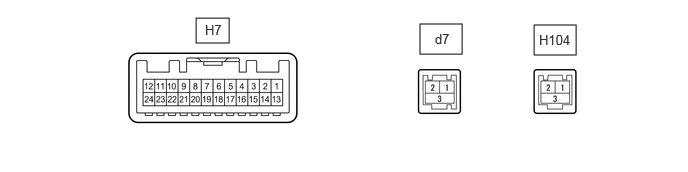
- MULTI-DISPLAY ASSEMBLY
Terminal No. (Symbol) Terminal Description Condition Specified Condition H7-2 (ILL+) - H7-13 (GND1) Illumination signal Ignition switch off
Light control switch offBelow 1 V Ignition switch off
Light control switch in tail or head position11 to 14 V H7-6 (TX1+) AVC-LAN communication signal - - H7-7 (TX+) AVC-LAN communication signal - - H7-11 (VMTI) - H7-13 (GND1) Visual mute signal When image on display switches 3.5 V or higher
→ Below 1 V
→ 3.5 V or higherH7-12 (B) - H7-13 (GND1) Power source (+B) Ignition switch off*1
Always*211 to 14 V*3
10.5 to 16 V*4H7-13 (GND1) - Body ground Ground Always Below 1 Ω H7-15 (ILL-) - H7-13 (GND1) Illumination signal Light control switch off Below 1 V Light control switch in tail or head position Pulse generation H7-18 (TX1-) AVC-LAN communication signal - - H7-19 (TX-) AVC-LAN communication signal - - H7-20 (CSLD) - Body ground Shield ground Always Below 1 Ω H7-21 (CGND) - Body ground Camera ground Always Below 1 Ω H7-24 (ACC) - H7-13 (GND1) Power source (ACC) Ignition switch off Below 1 V Ignition switch ACC 11 to 14 V*3
10.5 to 16 V*4d7-1 (GVI-) Video signal (Digital) - - d7-2 (GVI+) Video signal (Digital) - - d7-3 (GVGI) Shield ground - - H104-1 (GV+) Video signal (Digital) - - H104-2 (GV-) Video signal (Digital) - - H104-3 (GND) Shield ground - - - *1: for HV Model
- *2: for Gasoline Model
- *3: w/o Stop and Start System
- *4: w/ Stop and Start System
- DCM (TELEMATICS TRANSCEIVER)
Refer to TERMINALS OF ECU [12/2019 - 10/2022]
- COMBINATION METER ASSEMBLY
Refer to TERMINALS OF ECU [12/2019 - 11/2023]
- NO. 2 SKID CONTROL ECU (BRAKE ACTUATOR ASSEMBLY) (for HV Model)
Refer to TERMINALS OF ECU [12/2019 - ]
- SKID CONTROL ECU (BRAKE ACTUATOR ASSEMBLY) (for Gasoline Model)
Refer to TERMINALS OF ECU [12/2019 - ]
- TELEVISION DISPLAY ASSEMBLY (w/ Rear Seat Entertainment System)
Refer to TERMINALS OF ECU [12/2019 - 10/2022]
- PARKING ASSIST ECU
Refer to TERMINALS OF ECU [12/2019 - 10/2022]
- INTEGRATION CONTROL SUB-ASSEMBLY
Refer to TERMINALS OF ECU [12/2019 - 10/2022]
- HEADUP DISPLAY (METER MIRROR SUB-ASSEMBLY) (w/ Headup Display System)
Refer to TERMINALS OF ECU [12/2019 - ]