DTC Check / Clear [12/2019 - 10/2022]
- CHECK DTC (CHECK USING GTS)
- Connect the GTS to the DLC3.
- Turn the ignition switch to ON and wait for 90 seconds.
- Turn the GTS on.
- Enter the following menus: Body Electrical / Navigation System / Trouble Codes.
Body Electrical > Navigation System > Trouble Codes
- Check for DTCs, and then write them down.
- Check the details of the DTC(s).
- CLEAR DTC (CLEAR USING GTS)
- Connect the GTS to the DLC3.
- Turn the ignition switch to ON and wait for 90 seconds.
- Turn the GTS on.
- Enter the following menus: Body Electrical / Navigation System / Trouble Codes.
Body Electrical > Navigation System > Clear DTCs
- Clear the DTCs.
- START DIAGNOSTIC MODE
HINT:
- Illustrations may differ from the actual vehicle screen depending on the device settings and options. Therefore, some detailed areas may not be shown exactly the same as on the actual vehicle screen.
- If the system cannot enter diagnostic mode, inspect all AVC-LAN communication components and repair or replace the malfunctioning parts.
Refer to AVC-LAN Circuit [12/2019 - 10/2022]
- Start diagnostic mode at least 90 seconds after turning the ignition switch to ON. Otherwise, some items cannot be checked.
- There are 4 methods to start diagnostic mode. Start diagnostic mode by using one of them.
- Method 1:
- Turn the ignition switch to ON.
- While pressing and holding the "AUDIO" switch, operate the light control switch: Off → Tail → Off → Tail → Off → Tail → Off.
- Diagnostic mode will start and the "Service Menu" screen will be displayed.
- Method 2:
- Connect the GTS to the DLC3.
- Turn the ignition switch to ON.
- Turn the GTS on.
- Enter the following menus: Body Electrical / Navigation System / Utility / Diagnostic Mode.
Body Electrical > Navigation System > Utility
Tester Display Diagnostic Mode - Diagnostic mode will start and the "Service Menu" screen will be displayed.
- Method 3:NOTE:
- If the operation fails and diagnostic mode cannot be entered, turn the multi-display assembly screen display on and off once, and then perform the procedures listed below from the first step again. (Only turning the radio receiver assembly power supply on and off will not work.)
- Do not touch the multi-display except when necessary.
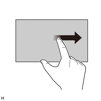
- Since the multi-display may recognize a pinch in/out or flick operation if operated with 2 fingers, always use 1 finger to operate it in diagnostic mode.
- Turn the ignition switch to ON.
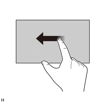
- Perform a flick operation on the multi-display screen from the left to the right 5 times and then perform a flick operation from the right to left 5 times with the screen and audio turned off as shown in the illustration.
HINT:
- Diagnostic mode can only be started if the above operation is completed within 15 seconds of the first flick from the left to the right.
- If the operation is not completed within 15 seconds of the first flick from the left to the right or fails, turn the screen and audio on and then off before attempting to start diagnostic mode again.
- Flick operations can be recognized anywhere within the touch area of the multi-display screen.
- Diagnostic mode will start and the "Service Menu" screen will be displayed.
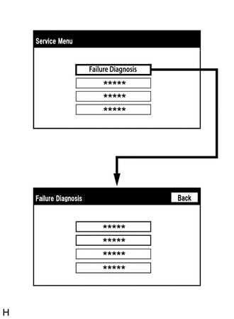
- FAILURE DIAGNOSIS
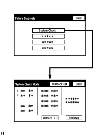
- SYSTEM CHECK
- CHECK DTC (CHECK USING SYSTEM CHECK MODE SCREEN)
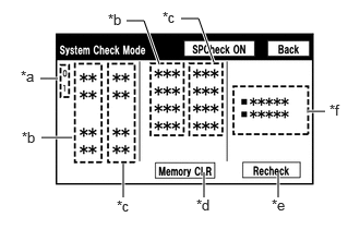
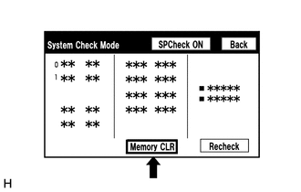
- System check mode screen descriptionSCREEN DESCRIPTION
Display Content *a: Node position number for devices connected to the MOST network. MOST network node position numbers are provided for devices connected to the MOST network. *b: Device Name List No. 1 - Device Name List No. 1 displays some of the devices that make up the navigation system.
- The names of the components from Device Name List No. 1 are shown in the following table.
*c: Check Result - Result codes for all devices are displayed.
- When "MOST" is displayed for the result, select "MOST" on the multi-display assembly to display the "MOST Line Check" screen.
*d: Memory Clear - Present and history DTCs and registered connected device names are cleared.
- Select "Memory CLR" for 3 seconds.
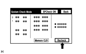
*e: Recheck - A system check will be performed again after the memory is cleared.
- "Recheck" will dim during a system check.
*f: Device Name List No. 2 - Device Name List No. 2 displays some of the devices that make up the navigation system.
- The names of the components from Device Name List No. 2 are shown in the following table.
*B: DEVICE NAME LIST NO. 1 DESCRIPTIONName Component Connection Method DCU Radio receiver assembly - AMP Stereo component amplifier assembly MOST communication line MEU Navigation ECU USB communication line Rr-TV Television display assembly AVC-LAN communication line DISP Multi-display assembly AVC-LAN communication line CAMERA-M Parking assist ECU CAN communication line *C: CHECK RESULT DESCRIPTIONResult Meaning Action OK The device does not respond with a DTC. - MOST MOST communication error Perform "MOST Line Check" to check the connection of each device on the MOST network. DETAIL The device responds with a DTC. Read the DTCs on the "Unit Check Mode" screen. NCON The device was previously present, but does not respond in diagnostic mode. - Check the vehicle wire harness.
- Check the AVC-LAN or MOST network of the device.
- Check the power supply circuit of the device.
NRES The device responds in diagnostic mode, but gives no DTC information. - Check the vehicle wire harness.
- Check the AVC-LAN or MOST network of the device.
- Check the power supply circuit of the device.
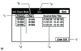
*F: DEVICE NAME LIST NO. 2 DESCRIPTIONName Component Connection Method DCM DCM (telematics transceiver) USB communication line - Unit check mode screen descriptionSCREEN DESCRIPTION
Display Content *a: Device name Target device *b: History DTC Diagnostic memory results and stored DTCs are displayed. *c: Current DTC DTCs output in the service check are displayed. *d: DTC DTC (Diagnostic Trouble Code) *e: Timestamp* The time and date of history DTCs are displayed. (The year is displayed in 2-digit format.) *f: Diagnosis clear Selecting "Code CLR" for 3 seconds clears the diagnostic memory data of the target device. (Both diagnostic system check result and the displayed data are cleared.) - *: w/ GPS Time Setting Function
HINT:
- This screen is updated once per second.
- A maximum of 6 DTCs can be displayed for history and present DTCs.
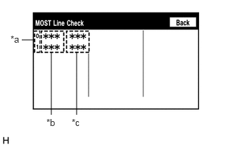
- MOST line check screen description
HINT:
- The inspection will be performed at the time the screen changes from "System Check Mode" to "MOST Line Check".
- The master unit checks the connection of each device on the MOST network.
SCREEN DESCRIPTIONDisplay Content *a: Node position number for devices connected to the MOST network. MOST node position numbers are provided for devices connected to the MOST network. *b: Device Name List - Device Name List displays some of the devices that make up the navigation system.
- The names of the components from Device Name List are shown in the following table.
*c: Check Result The master unit displays the check result on the screen based on the response information from each slave unit. *B: DEVICE NAME LISTName Component DCU Radio receiver assembly AMP Stereo component amplifier assembly *C: CHECK RESULTResult Meaning OK There was a response for the connection check during the MOST line check. NCON There was no response for the connection check during the MOST line check. HINT:
The device name and result will not be displayed if there is no system registration record and no response for the connection check during the MOST line check even if the device is connected to the MOST network.
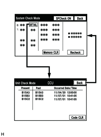
- Read the system check result.
- If the check result is "DETAIL", select the displayed check result to view the results on the "Unit Check Mode" screen and record them.NOTE:
A maximum of 6 DTCs can be displayed for history and present DTCs on the "Unit Check Mode" screen. Therefore, when 6 DTCs are displayed, troubleshoot those DTCs first and then check the "Unit Check Mode" screen again to see if any other DTCs are displayed.
HINT:
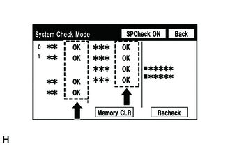
- When all results are "OK", no DTCs are present.
- When "MOST" is displayed for the result, select "MOST" to display the "MOST Line Check" screen and check the MOST network.
- Changing to the "MOST Line Check" screen is possible only when the MOST network is malfunctioning and "MOST" is displayed for the result.
- If the MOST network had a malfunction in the past, DTCs will be displayed in the Memory column.
- When "NCON" is displayed for all devices connected via AVC-LAN communication, or when all device names are not displayed, check if there is a short in an AVC-LAN line or devices connected to the AVC-LAN. Repair or replace parts as necessary.
Refer to AVC-LAN Circuit [12/2019 - 10/2022]
- When proceeding to view the results of another device, select "Back" to return to the "System Check Mode" screen. Repeat the above step to view the results of other devices.
- Check the details of the DTC(s).
- If the check result is "DETAIL", select the displayed check result to view the results on the "Unit Check Mode" screen and record them.
- System check mode screen description
- DTC CLEAR/RECHECK (CLEAR USING SYSTEM CHECK MODE SCREEN)
- Clear DTCs
- Select "Memory CLR" for 3 seconds.
- Check that the check results are cleared.
HINT:
- To clear the DTCs for a specific device, use the "Unit Check Mode" screen.
- When clearing the DTCs using the "Unit Check Mode" screen, select "Code CLR" for 3 seconds.
- Recheck
- Select "Recheck".
- Check that all diagnostic codes are "OK" when the check results are displayed. If a result other than "OK" is displayed, perform troubleshooting again.
HINT:
When the DTCs are cleared using the "Unit Check Mode" screen, select "Back" to return to the "System Check Mode" screen and perform this operation.
- Clear DTCs
- FINISH DIAGNOSTIC MODE
- Turn the ignition switch off.