DTC B153A: GVIF Disconnected (from Extension Module to H/U) [12/2019 - 10/2022]: Procedure
- CHECK DTC
- Clear the DTCs.
Body Electrical > Navigation System > Clear DTCs
- Press the "MAP" switch and check for DTCs.
Body Electrical > Navigation System > Trouble Codes
OK
No DTCs are output.
Result
Proceed to OK NG
Result:
OK
USE SIMULATION METHOD TO CHECK. Refer to HOW TO PROCEED WITH TROUBLESHOOTING [12/2019 - ]
Result:
NG
See step 2
- Clear the DTCs.
- CHECK HARNESS OR CONNECTOR (RADIO RECEIVER ASSEMBLY - NAVIGATION ECU)
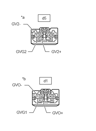
- Disconnect the d5 radio receiver assembly connector.
- Disconnect the d1 navigation ECU connector.
*a Front view of wire harness connector
(to Radio Receiver Assembly)*b Front view of wire harness connector
(to Navigation ECU) - Measure the resistance according to the value(s) in the table below.
Standard Resistance
Tester Connection Condition Specified Condition d5-1 (GV2-) - d1-1 (GVO-) Always Below 1 Ω d5-2 (GV2+) - d1-2 (GVO+) Always Below 1 Ω d5-3 (GVG2) - d1-3 (GVG1) Always Below 1 Ω Result
Proceed to OK NG
Result:
NG
REPAIR OR REPLACE HARNESS OR CONNECTOR
Result:
OK
See step 3
- REPLACE NAVIGATION ECU
- Replace the navigation ECU with a new or known good one.
Refer to REMOVAL [12/2019 - 10/2022]
Result
Proceed to NEXT
Result:
NEXT
See step 4
- Replace the navigation ECU with a new or known good one.
- CHECK DTC
- Clear the DTCs.
Body Electrical > Navigation System > Clear DTCs
- Press the "MAP" switch and check for DTCs.
Body Electrical > Navigation System > Trouble Codes
OK
No DTCs are output.
Result
Proceed to OK NG
Result:
OK
END (NAVIGATION ECU IS DEFECTIVE)
Result:
NG
REPLACE RADIO RECEIVER ASSEMBLY. Refer to REMOVAL [12/2019 - 10/2022]
- Clear the DTCs.