DTC B1543: Extension Module Disconnected 2 [12/2019 - 10/2022]: Procedure
- CHECK MAP SCREEN
- Turn the ignition switch to ACC and wait for 90 seconds.
- Press the "MAP" switch and check that the map screen is displayed normally.
Result
Result Proceed to Map screen is displayed normally A Map screen is not displayed normally B HINT:
- This DTC may be stored due to environmental reasons such as electrical noise or interference.
- Clear past DTCs when the map screen is displayed normally. (Codes stored due to past environmental factors)
Result:
A
USE SIMULATION METHOD TO CHECK. Refer to HOW TO PROCEED WITH TROUBLESHOOTING [12/2019 - ]
Result:
B
See step 2
- CHECK DTC
- Clear the DTCs.
Body Electrical > Navigation System > Clear DTCs
- Turn the ignition switch off.
- Turn the ignition switch to ON and wait for 90 seconds.
- Recheck for DTCs and check that no DTCs are output.
Body Electrical > Navigation System > Trouble Codes
OK
No DTCs are output.
Result
Proceed to OK NG
Result:
OK
USE SIMULATION METHOD TO CHECK. Refer to HOW TO PROCEED WITH TROUBLESHOOTING [12/2019 - ]
Result:
NG
See step 3
- Clear the DTCs.
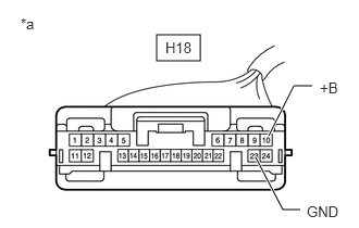
- CHECK HARNESS AND CONNECTOR (NAVIGATION ECU - AUXILIARY BATTERY AND BODY GROUND)
- Disconnect the H18 navigation ECU connector.
*a Front view of wire harness connector
(to Navigation ECU) - Measure the resistance according to the value(s) in the table below.
Standard Resistance
Tester Connection Condition Specified Condition H18-23 (GND) - Body ground Always Below 1 Ω - Measure the voltage according to the value(s) in the table below.
Standard Voltage
Tester Connection Condition Specified Condition H18-10 (+B) - Body ground*1 Ignition switch off 11 to 14 V H18-10 (+B) - Body ground*2 Always 11 to 14 V*3
10.5 to 16 V*4- *1: for HV Model
- *2: for Gasoline Model
- *3: w/o Stop and Start System
- *4: w/ Stop and Start System
Result
Result Proceed to OK A NG (w/o Stop and Start System) B NG (w/ Stop and Start System) C
Result:
B
REPAIR OR REPLACE HARNESS OR CONNECTOR
Result:
C
GO TO STOP AND START SYSTEM. Refer to HOW TO PROCEED WITH TROUBLESHOOTING [12/2019 - 10/2022]
Result:
A
See step 4
- Disconnect the H18 navigation ECU connector.
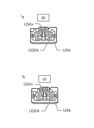
- CHECK HARNESS AND CONNECTOR (RADIO RECEIVER ASSEMBLY - NAVIGATION ECU)
- Disconnect the d5 radio receiver assembly connector.
- Disconnect the d1 navigation ECU connector.
*a Front view of wire harness connector
(to Radio Receiver Assembly)*b Front view of wire harness connector
(to Navigation ECU) - Measure the resistance according to the value(s) in the table below.
Standard Resistance
Tester Connection Condition Specified Condition d5-4 (US4+) - d1-4 (US4+) Always Below 1 Ω d5-5 (US4-) - d1-5 (US4-) Always Below 1 Ω d5-6 (UGD4) - d1-6 (UGD4) Always Below 1 Ω Result
Proceed to OK NG
Result:
NG
REPAIR OR REPLACE HARNESS OR CONNECTOR
Result:
OK
See step 5
- REPLACE NAVIGATION ECU
- Replace the navigation ECU with a new or known good one.
Refer to REMOVAL [12/2019 - 10/2022]
Result
Proceed to NEXT
Result:
NEXT
See step 6
- Replace the navigation ECU with a new or known good one.
- CHECK DTC
- Clear the DTCs.
Body Electrical > Navigation System > Clear DTCs
- Turn the ignition switch off.
- Turn the ignition switch to ON and wait for 90 seconds.
- Recheck for DTCs and check that no DTCs are output.
Body Electrical > Navigation System > Trouble Codes
OK
No DTCs are output.
Result
Proceed to OK NG
Result:
OK
END (NAVIGATION ECU IS DEFECTIVE)
Result:
NG
REPLACE RADIO RECEIVER ASSEMBLY. Refer to REMOVAL [12/2019 - 10/2022]
- Clear the DTCs.