DTC B1579: Voice Recognition Microphone Disconnected [12/2019 - 10/2022]: Procedure
- INSPECT RADIO RECEIVER ASSEMBLY
- Measure the resistance according to the value(s) in the table below.
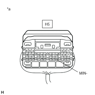
*a Component with harness connected
(Radio Receiver Assembly)Standard Resistance
Tester Connection Condition Specified Condition H5-22 (MIN-) - Body ground Always Below 1 Ω Result
Proceed to OK NG
Result:
NG
REPLACE RADIO RECEIVER ASSEMBLY. Refer to REMOVAL [12/2019 - 10/2022]
Result:
OK
See step 2
- Measure the resistance according to the value(s) in the table below.
- CHECK HARNESS AND CONNECTOR (DCM (TELEMATICS TRANSCEIVER) - TELEPHONE MICROPHONE ASSEMBLY)
- Disconnect the H11 DCM (telematics transceiver) connector.
- Disconnect the R12 telephone microphone assembly connector.
- Measure the resistance according to the value(s) in the table below.
Standard Resistance
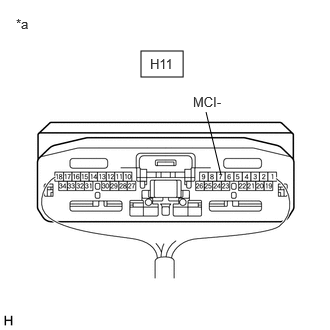
Tester Connection Condition Specified Condition H11-7 (MCI-) - R12-4 (MCO-) Always Below 1 Ω H11-7 (MCI-) or R12-4 (MCO-) - Body ground Always 10 kΩ or higher Result
Proceed to OK NG
Result:
NG
REPAIR OR REPLACE HARNESS OR CONNECTOR
Result:
OK
See step 3
- CHECK HARNESS AND CONNECTOR (RADIO RECEIVER ASSEMBLY - DCM (TELEMATICS TRANSCEIVER))
- Disconnect the H5 radio receiver assembly connector.
- Disconnect the H11 DCM (telematics transceiver) connector.
- Measure the resistance according to the value(s) in the table below.
Standard Resistance
Tester Connection Condition Specified Condition H5-22 (MIN-) - H11-32 (MCO-) Always Below 1 Ω H5-22 (MIN-) or H11-32 (MCO-) - Body ground Always 10 kΩ or higher Result
Proceed to OK NG
Result:
NG
REPAIR OR REPLACE HARNESS OR CONNECTOR
Result:
OK
See step 4
- CHECK HARNESS AND CONNECTOR (RADIO RECEIVER ASSEMBLY - TELEPHONE MICROPHONE ASSEMBLY)
- Disconnect the H5 radio receiver assembly connector.
- Disconnect the R12 telephone microphone assembly connector.
- Measure the resistance according to the value(s) in the table below.
Standard Resistance
Tester Connection Condition Specified Condition H5-25 (SNS2) - R12-3 (SNS2) Always Below 1 Ω H5-25 (SNS2) or R12-3 (SNS2) - Body ground Always 10 kΩ or higher Result
Proceed to OK NG
Result:
NG
REPAIR OR REPLACE HARNESS OR CONNECTOR
Result:
OK
See step 5
- INSPECT DCM (TELEMATICS TRANSCEIVER)
- Connect the H11 DCM (telematics transceiver) connector.
*a Component with harness connected
(DCM (Telematics Transceiver)) - Connect the H5 radio receiver assembly connector.
- Measure the resistance according to the value(s) in the table below.
Standard Resistance
Tester Connection Condition Specified Condition H11-7 (MCI-) - Body ground Always Below 1 Ω Result
Proceed to OK NG
Result:
NG
REPLACE DCM (TELEMATICS TRANSCEIVER). Refer to REMOVAL [12/2019 - 10/2022]
Result:
OK
See step 6
- Connect the H11 DCM (telematics transceiver) connector.
- INSPECT TELEPHONE MICROPHONE ASSEMBLY
- Remove the telephone microphone assembly.
Refer to REMOVAL [12/2019 - 10/2022]
- Measure the resistance according to the value(s) in the table below.
Standard Resistance
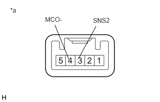
Tester Connection Condition Specified Condition 3 (SNS2) - 4 (MCO-) Always Below 1 Ω *a Component without harness connected
(Telephone Microphone Assembly)Result
Proceed to OK NG
Result:
OK
REPLACE RADIO RECEIVER ASSEMBLY. Refer to REMOVAL [12/2019 - 10/2022]
Result:
NG
REPLACE TELEPHONE MICROPHONE ASSEMBLY. Refer to REMOVAL [12/2019 - 10/2022]
- Remove the telephone microphone assembly.