DTC B15C2: Speed Signal Malfunction [12/2019 - 10/2022]: Procedure
- CHECK DTC
- Clear the DTCs.
Body Electrical > Navigation System > Clear DTCs
- Recheck for DTCs and check that no DTCs are output.
Body Electrical > Navigation System > Trouble Codes
OK
No DTCs are output.
Result
Proceed to OK NG
Result:
OK
USE SIMULATION METHOD TO CHECK. Refer to HOW TO PROCEED WITH TROUBLESHOOTING [12/2019 - ]
Result:
NG
See step 2
- Clear the DTCs.
- CHECK VEHICLE SENSOR (OPERATION CHECK)
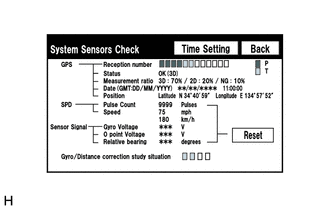
- Enter the "System Sensors Check" screen. Refer to Check GPS & Vehicle Sensors in Operation Check.
Refer to OPERATION CHECK [12/2019 - 10/2022]
- While driving the vehicle, compare the value of "Speed" to the reading on the speedometer. Check if these readings are almost equal.
HINT:
The combination meter assembly receives the vehicle speed signal from the skid control ECU via CAN communication. Therefore, perform the following procedure inspection referring to values in the Data List of the skid control ECU because it is the source of the vehicle speed signal.
OK
Vehicle speed displayed on the "System Sensors Check" screen is almost the same as the actual vehicle speed measured using the GTS.
for HV Model: Refer to DATA LIST / ACTIVE TEST [12/2019 - 11/2023]
for Gasoline Model: Refer to DATA LIST / ACTIVE TEST [12/2019 - 11/2023]
Result
Proceed to OK NG
Result:
OK
See step 5
Result:
NG
See step 3
- Enter the "System Sensors Check" screen. Refer to Check GPS & Vehicle Sensors in Operation Check.
- CHECK COMBINATION METER ASSEMBLY (OUTPUT WAVEFORM)
- Check the output waveform.
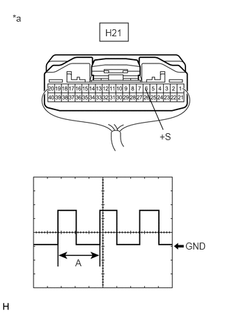
*a Component with harness connected
(Combination Meter Assembly)- Remove the combination meter assembly with the connector(s) still connected.
- Connect an oscilloscope to terminal H21-6 (+S) and body ground.
- Turn the ignition switch to ON.
- Turn a wheel slowly.
- Check the signal waveform according to the condition(s) in the table below.
Item Condition Measurement terminal H21-6 (+S) - Body ground Tool setting 5 V/DIV., 20 ms./DIV. Vehicle condition Wheel being rotated OK
The waveform is similar to that shown in the illustration.
HINT:
When the system is functioning normally, one wheel revolution generates 4 pulses. As the vehicle speed increases, the width indicated by (A) in the illustration narrows.
Result
Proceed to OK NG
Result:
NG
GO TO METER / GAUGE SYSTEM. Refer to HOW TO PROCEED WITH TROUBLESHOOTING [12/2019 - ]
Result:
OK
See step 4
- Check the output waveform.
- CHECK HARNESS AND CONNECTOR (NAVIGATION ECU - COMBINATION METER ASSEMBLY)
- Disconnect the H18 navigation ECU connector.
- Disconnect the H21 combination meter assembly connector.
- Measure the resistance according to the value(s) in the table below.
Standard Resistance
Tester Connection Condition Specified Condition H18-9 (SPD) - H21-6 (+S) Always Below 1 Ω H18-9 (SPD) or H21-6 (+S) - Body ground Always 10 kΩ or higher Result
Proceed to OK NG
Result:
NG
REPAIR OR REPLACE HARNESS OR CONNECTOR
Result:
OK
See step 5
- REPLACE NAVIGATION ECU
- Replace the navigation ECU with a new or known good one.
Refer to REMOVAL [12/2019 - 10/2022]
Result
Proceed to NEXT
Result:
NEXT
See step 6
- Replace the navigation ECU with a new or known good one.
- CHECK DTC
- Clear the DTCs.
Body Electrical > Navigation System > Clear DTCs
- Recheck for DTCs and check that no DTCs are output.
Body Electrical > Navigation System > Trouble Codes
OK
No DTCs are output.
Result
Proceed to OK NG
Result:
OK
END (NAVIGATION ECU IS DEFECTIVE)
Result:
NG
REPLACE RADIO RECEIVER ASSEMBLY. Refer to REMOVAL [12/2019 - 10/2022]
- Clear the DTCs.