DTC B15D0: MOST Communication Malfunction [12/2019 - 10/2022]: Procedure
- CHECK DTC
- Check for DTCs.
Body Electrical > Navigation System > Trouble Codes
Result
Result Proceed to DTC B15C3 and B15D3 are not output A DTC B15C3 is output B DTC B15D3 is output C HINT:
- If a short occurs in a speaker circuit, the sound output from the speakers will become very low or will stop and DTC B15C3 will be stored.
In this case, if the audio system volume is increased, current in the speaker circuit will increase more than necessary.
To prevent the current from becoming excessively high, when it increases to a certain amount, operation of the stereo component amplifier assembly will be suspended.
If operation is suspended, MOST communication will become impossible, the navigation system will not operate normally and DTC B15D0 will be stored.
- If DTC B15C3 and B15D3 are output at the same time, perform troubleshooting for DTC B15C3 first.
- If a short occurs in a speaker circuit, the sound output from the speakers will become very low or will stop and DTC B15C3 will be stored.
Result:
B
GO TO DTC B15C3. Refer to DTC B15C3: Speaker Output Short [12/2019 - 10/2022]
Result:
C
GO TO B15D3. Refer to DTC B15D3: Stereo Component Amplifier Disconnected [12/2019 - 10/2022]
Result:
A
See step 2
- Check for DTCs.
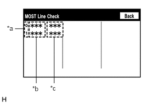
- PERFORM MOST LINE CHECK
- Enter the "MOST Line Check" screen. Refer to Check DTC (Check Using System Check Mode Screen) in DTC Check / Clear.
*a MOST Network Device Node Position Number *b Device Name *c Result Refer to DTC CHECK / CLEAR [12/2019 - 10/2022]
HINT:
"MOST" is displayed on "System Check Mode" screen when the MOST network is malfunctioning.
Result
Result Proceed to "OK" is displayed for all items. A "NCON" is displayed for "AMP". B
Result:
B
See step 5
Result:
A
See step 3
- Enter the "MOST Line Check" screen. Refer to Check DTC (Check Using System Check Mode Screen) in DTC Check / Clear.
- CHECK HARNESS AND CONNECTOR (RADIO RECEIVER ASSEMBLY - STEREO COMPONENT AMPLIFIER ASSEMBLY)
- Disconnect the H102 radio receiver assembly connector.
- Disconnect the M99 stereo component amplifier assembly connector.
- Measure the resistance according to the value(s) in the table below.
Standard Resistance
Tester Connection Condition Specified Condition H102-2 (MI+) - M99-5 (MO+) Always Below 1 Ω H102-3 (MI-) - M99-6 (MO-) Always Below 1 Ω H102-4 (SLDI) - M99-7 (SLDO) Always Below 1 Ω H102-5 (MO+) - M99-2 (MI+) Always Below 1 Ω H102-6 (MO-) - M99-3 (MI-) Always Below 1 Ω H102-7 (SLDO) - M99-4 (SLDI) Always Below 1 Ω H102-2 (MI+) or M99-5 (MO+) - Body ground Always 10 kΩ or higher H102-3 (MI-) or M99-6 (MO-) - Body ground Always 10 kΩ or higher H102-4 (SLDI) or M99-7 (SLDO) - Body ground Always 10 kΩ or higher H102-5 (MO+) or M99-2 (MI+) - Body ground Always 10 kΩ or higher H102-6 (MO-) or M99-3 (MI-) - Body ground Always 10 kΩ or higher H102-7 (SLDO) or M99-4 (SLDI) - Body ground Always 10 kΩ or higher Result
Proceed to OK NG
Result:
NG
REPAIR OR REPLACE HARNESS OR CONNECTOR
Result:
OK
See step 4
- REPLACE STEREO COMPONENT AMPLIFIER ASSEMBLY
- Replace the stereo component amplifier assembly with a new or known good one.
Refer to REMOVAL [12/2019 - ]
- Clear the DTCs.
Body Electrical > Navigation System > Clear DTCs
- Recheck for DTCs and check that no DTCs are output.
Body Electrical > Navigation System > Trouble Codes
OK
No DTCs are output.
Result
Proceed to OK NG
Result:
OK
END
Result:
NG
REPLACE RADIO RECEIVER ASSEMBLY. Refer to REMOVAL [12/2019 - 10/2022]
- Replace the stereo component amplifier assembly with a new or known good one.
- CHECK HARNESS AND CONNECTOR (STEREO COMPONENT AMPLIFIER ASSEMBLY WAKE UP LINE)
- Disconnect the M99 stereo component amplifier assembly connector.
- Measure the voltage according to the value(s) in the table below.
Standard Voltage
Tester Connection Condition Specified Condition M99-8 (WUI) - Body ground Ignition switch ACC 4.5 V or higher Result
Proceed to OK NG
Result:
OK
REPLACE STEREO COMPONENT AMPLIFIER ASSEMBLY. Refer to REMOVAL [12/2019 - ]
Result:
NG
REPAIR OR REPLACE HARNESS OR CONNECTOR