Terminals Of Ecu [12/2019 - 10/2022]
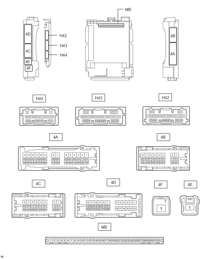
- CHECK MAIN BODY ECU (MULTIPLEX NETWORK BODY ECU) AND INSTRUMENT PANEL JUNCTION BLOCK ASSEMBLY
- Disconnect the instrument panel junction block assembly and main body ECU (multiplex network body ECU) connectors.
- Measure the voltage and resistance according to the value(s) in the table below.
Terminal No. (Symbol) Terminal Description Condition Specified Condition 4B-3 - Body ground Ground Always Below 1 Ω 4C-1 - Body ground Auxiliary battery power supply Ignition switch off*1
Always*211 to 14 V 4F-1 - Body ground Auxiliary battery power supply Ignition switch off*1
Always*211 to 14 V H42-19 (GND2) - Body ground Ground Always Below 1 Ω - *1: for HV Model
- *2: for Gasoline Model
- Connect the instrument panel junction block assembly and main body ECU (multiplex network body ECU) connectors.
- Measure the voltage and check for pulses according to the value(s) in the table below.
Terminal No. (Symbol) Terminal Description Condition Specified Condition 4A-40 - Body ground* ACC power supply Ignition switch off Below 1 V Ignition switch ACC 11 to 14 V 4B-11 - Body ground Taillight and rear side marker light drive output Taillights on 11 to 14 V Taillights off Below 1 V 4C-19 - Body ground R shift position switch signal Ignition switch off, reverse (R) not selected Below 1 V Ignition switch ON, reverse (R) selected 11 to 14 V 4C-23 - Body ground* IG power supply Ignition switch off Below 1 V Ignition switch ON 11 to 14 V 4C-25 - Body ground FOG FR relay drive output Taillights on, fog light switch in front position Below 1 V Taillights on, fog light switch in off position 11 to 14 V 4C-31 - Body ground H-LP LH relay drive output - Ignition switch ON or within 15 seconds after ignition switch turned off
- Taillights on
Below 1 V - 15 seconds or more after ignition switch turned off
- Taillights off
11 to 14 V 4C-32 - Body ground Front side marker lights drive output Taillights on 11 to 14 V Taillights off Below 1 V 4D-10 - Body ground Back-up lights drive output Ignition switch off, reverse (R) not selected Below 1 V Ignition switch ON, reverse (R) selected 11 to 14 V 4D-30 - Body ground Taillight, rear side marker light and license plate lights drive output Taillights on 11 to 14 V Taillights off Below 1 V H43-12 (HRY2) - Body ground H-LP RH relay drive output - Ignition switch ON or within 15 seconds after ignition switch turned off
- Taillights on
Below 1 V - 15 seconds or more after ignition switch turned off
- Taillights off
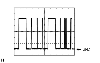
11 to 14 V H43-16 (HEAD) - Body ground Light control switch head position input Light control switch in head position Below 1 V Light control switch not in head position 11 to 14 V H43-23 (CLTB) - H43-25 (CLTE) Automatic light control sensor power supply output Ignition switch ON 11 to 14 V H43-24 (CLTS) - Body ground Automatic light control sensor signal input Ignition switch off Below 1 V Ignition switch ON Pulse generation
(See waveform 1)H43-26 (AHBI) - Body ground Auto high beam switch signal input Auto high beam switch on Below 1 V Auto high beam switch off 11 to 14 V H44-21 (AHID) - Body ground Auto high beam switch indicator drive output Ignition switch ON, auto high beam switch on Below 1 V Ignition switch ON, auto high beam switch off 11 to 14 V - *: for Gasoline Model
- CHECK HEADLIGHT ECU SUB-ASSEMBLY LH
- Disconnect the A15 headlight ECU sub-assembly LH connector.
- Measure the voltage and resistance on the wire harness side connector according to the value(s) in the table below.
Terminal No. (Symbol) Terminal Description Condition Specified Condition A15-4 (IG) - Body ground Ignition power supply Ignition switch off Below 1 V Ignition switch ON 11 to 14 V A15-12 (GND) - Body ground Ground Always Below 1 Ω A15-13 (ECUB) - Body ground Auxiliary battery power supply - 15 seconds or more after ignition switch turned off
- Taillights off
Below 1 V - Ignition switch ON or within 15 seconds after ignition switch turned off
- Taillights on
11 to 14 V - Connect the A15 headlight ECU sub-assembly LH connector.
HINT:
- Since the A headlight ECU sub-assembly LH connector is a waterproof type connector, the voltage and pulses cannot be checked directly. The values listed are for reference only.
- Since the B and C headlight ECU sub-assembly LH connectors are connected inside the headlight assembly, the voltage and pulses cannot be checked directly. The values listed are for reference only.
- Measure the voltage and check of pulses according to the value(s) in the table below.
Terminal No. (Symbol) Terminal Description Condition Specified Condition A15-11 (TNS) - Body ground Front turn signal light signal input Ignition switch ON, front turn signal light off Below 1 V Ignition switch ON, front turn signal light blinking 11 to 14 V ←→ Below 1 V A15-16 (SBR) - A15-15 (SGR) Rear height control sensor sub-assembly LH power supply Ignition switch ON 4.75 to 5.25 V A15-17 (SHRL) - A15-15 (SGR) Rear height control sensor sub-assembly LH signal input Ignition switch ON, vehicle unloaded, vehicle stopped Approximately 2.5 V
(value decreases as the front of the vehicle is raised)A15-19 (LINS) - Body ground LIN communication line Ignition switch off Below 1 V Ignition switch ON Pulse generation A15-20 (LINL) - Body ground LIN communication line Ignition switch off Below 1 V Ignition switch ON Pulse generation A15-23 (CANL) - Body ground CAN communication line Ignition switch off Below 1 V Ignition switch ON Pulse generation A15-24 (CANH) - Body ground CAN communication line Ignition switch off Below 1 V Ignition switch ON Pulse generation B-2 (LOLED2) - B-3 (LOLED1) Low beam headlights drive output Low beam headlights off Below 1 V Low beam headlights on 10 to 20 V B-9 (ACTBI) - B-17 (ACTGI) Headlight swivel and leveling motor power source Ignition switch off Below 1 V Ignition switch ON 11 to 14 V B-10 (DRL/CLL+) - B-1 (DRL/CLL-) Parking lights/daytime running lights power source Parking lights and daytime running lights off Below 1 V Parking lights and daytime running lights on 11 to 14 V B-16 (PWM1) - B-1 (DRL/CLL-) Parking lights/daytime running lights control signal output Parking lights and daytime running lights off Below 1 V Parking lights and daytime running lights on Pulse generation B-19 (HI_SOL+) - B-11 (HI_SOL-) High beam headlights drive output High beam headlights off Below 1 V High beam headlights on 11 to 14 V B-20 (TURN+) - B-1 (DRL/CLL-) Front turn signal light signal output Ignition switch ON, front turn signal light off Below 1 V Ignition switch ON, front turn signal light blinking 11 to 14 V ←→ Below 1 V C-4 (LINSI) - Body ground LIN communication line Ignition switch off Below 1 V Ignition switch ON Pulse generation C-7 (CLL+) - B-1 (DRL/CLL-) Parking lights drive output Parking lights off Below 1 V Parking lights on 11 to 14 V C-13 (LINLI) - Body ground LIN communication line Ignition switch off Below 1 V Ignition switch ON Pulse generation
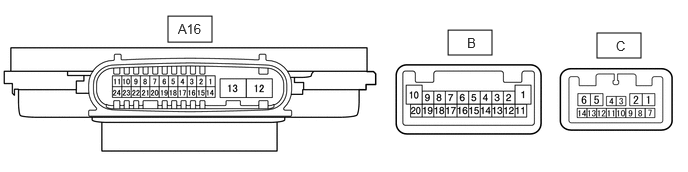
- CHECK HEADLIGHT ECU SUB-ASSEMBLY RH
- Disconnect the A16 headlight ECU sub-assembly RH connector.
- Measure the voltage and resistance on the wire harness side connector according to the value(s) in the table below.
Terminal No. (Symbol) Terminal Description Condition Specified Condition A16-4 (IG) - Body ground Ignition power supply Ignition switch off Below 1 V Ignition switch ON 11 to 14 V A16-12 (GND) - Body ground Ground Always Below 1 Ω A16-13 (ECUB) - Body ground Auxiliary battery power supply - 15 seconds or more after ignition switch turned off
- Taillights off
Below 1 V - Ignition switch ON or within 15 seconds after ignition switch turned off
- Taillights on
11 to 14 V - Connect the A16 headlight ECU sub-assembly RH connector.
HINT:
- Since the A16 headlight ECU sub-assembly RH connector is a waterproof type connector, the voltage and pulses cannot be checked directly. The values listed are for reference only.
- Since the B and C headlight ECU sub-assembly RH connectors are connected inside the headlight assembly, the voltage and pulses cannot be checked directly. The values listed are for reference only.
- Measure the voltage and check of pulses according to the value(s) in the table below.
Terminal No. (Symbol) Terminal Description Condition Specified Condition A16-11 (TNS) - Body ground Front turn signal light signal input Ignition switch ON, front turn signal light off Below 1 V Ignition switch ON, front turn signal light blinking 11 to 14 V ←→ Below 1 V A16-19 (LINS) - Body ground LIN communication line Ignition switch off Below 1 V Ignition switch ON Pulse generation A16-20 (LINL) - Body ground LIN communication line Ignition switch off Below 1 V Ignition switch ON Pulse generation A16-23 (CANL) - Body ground CAN communication line Ignition switch off Below 1 V Ignition switch ON Pulse generation A16-24 (CANH) - Body ground CAN communication line Ignition switch off Below 1 V Ignition switch ON Pulse generation B-2 (LOLED2) - B-3 (LOLED1) Low beam headlights drive output Low beam headlights off Below 1 V Low beam headlights on 10 to 20 V B-9 (ACTBI) - B-17 (ACTGI) Headlight swivel and leveling motor power source Ignition switch off Below 1 V Ignition switch ON 11 to 14 V B-10 (DRL/CLL+) - B-1 (DRL/CLL-) Parking lights/daytime running lights power source Parking lights and daytime running lights off Below 1 V Parking lights and daytime running lights on 11 to 14 V B-16 (PWM1) - B-1 (DRL/CLL-) Parking lights/daytime running lights control signal output Parking lights and daytime running lights off Below 1 V Parking lights and daytime running lights on Pulse generation B-19 (HI_SOL+) - B-11 (HI_SOL-) High beam headlights drive output High beam headlights off Below 1 V High beam headlights on 11 to 14 V B-20 (TURN+) - B-1 (DRL/CLL-) Front turn signal light signal output Ignition switch ON, front turn signal light off Below 1 V Ignition switch ON, front turn signal light blinking 11 to 14 V ←→ Below 1 V C-4 (LINSI) - Body ground LIN communication line Ignition switch off Below 1 V Ignition switch ON Pulse generation C-7 (CLL+) - B-1 (DRL/CLL-) Parking lights drive output Parking lights off Below 1 V Parking lights on 11 to 14 V C-13 (LINLI) - Body ground LIN communication line Ignition switch off Below 1 V Ignition switch ON Pulse generation
- CHECK COMBINATION METER ASSEMBLY
Refer to TERMINALS OF ECU [12/2019 - 11/2023]
- CHECK FORWARD RECOGNITION CAMERA
Refer to TERMINALS OF ECU [12/2019 - ]
- CHECK STEERING SENSOR
for HV Model: Refer to TERMINALS OF ECU [12/2019 - 10/2021] , or refer to TERMINALS OF ECU [10/2021 - 10/2022]
for Gasoline Model: Refer to TERMINALS OF ECU [12/2019 - 10/2022]