On-Vehicle Inspection [12/2019 - ]: Procedure
- INSPECT PRESSURE SENSOR
- Check the auxiliary battery voltage.
Standard Voltage
11 to 14 V (while the ignition switch is off)
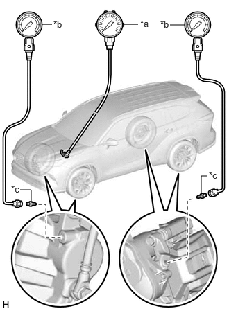
- Set a pedal effort gauge and SST.
HINT:
Simultaneously measure the brake fluid pressure of all 4 wheels, or 2 wheels at a time.
- Set a pedal effort gauge and SST.
- SST: 09709-29018
- 09709-00060
*a Pedal Effort Gauge *b SST (LSPV Gauge) *c SST (No. 1 Nipple) - SST: 09709-29018
- Move the shift lever to P and apply the parking brake.
- Bleed air from SST (LSPV gauge).
Refer to BLEEDING [12/2019 - ]
- Set a pedal effort gauge and SST.
- Inspect the master cylinder sensor 1, reaction force pressure and servo pressure.
- Check the value output from "Master Cylinder Sensor 1", "Reaction Force Pressure" and "Servo Pressure" by depressing the brake pedal.
Chassis > Brake/EPB > Data List
Tester Display Master Cylinder Sensor 1 Chassis > Brake Booster > Data List
Tester Display Reaction Force Pressure Servo Pressure Standard Result
Pedal Effort Reaction Force Pressure
(MPa)Servo Pressure
(MPa)Master Cylinder Sensor 1
(MPa)Front Left Wheel Hydraulic Pressure Front Right Wheel Hydraulic Pressure 50 N (5 kgf, 11.2 lbf) 0.00 to 0.68 0.30 to 4.30 0.00 to 4.00 0.00 to 4.00 MPa (0.0 to 40.8 kgf/cm2 , 0 to 580 psi) 0.0 to 4.0 MPa (0.0 to 40.8 kgf/cm2 , 0 to 580 psi) 100 N (10 kgf, 22.5 lbf) 0.61 to 1.41 3.23 to 7.23 2.93 to 6.93 2.93 to 6.93 MPa (29.9 to 70.7 kgf/cm2 , 425 to 1005 psi) 2.93 to 6.93 MPa (29.9 to 70.7 kgf/cm2 , 425 to 1005 psi) 150 N (15 kgf, 33.7 lbf) 1.29 to 2.09 5.52 to 9.52 5.22 to 9.22 5.22 to 9.22 MPa (53.2 to 94.0 kgf/cm2 , 757 to 1337 psi) 5.22 to 9.22 MPa (53.2 to 94.0 kgf/cm2 , 757 to 1337 psi) 200 N (20 kgf, 45.0 lbf) 1.96 to 2.76 7.30 to 11.30 7.00 to 11.00 7.0 to 11.0 MPa (71.4 to 112.2 kgf/cm2 , 1015 to 1595 psi) 7.0 to 11.0 MPa (71.4 to 112.2 kgf/cm2 , 1015 to 1595 psi) Standard Result
Pedal Effort Reaction Force Pressure
(MPa)Servo Pressure
(MPa)Master Cylinder Sensor 1
(MPa)Rear Left Wheel Hydraulic Pressure Rear Right Wheel Hydraulic Pressure 50 N (5 kgf, 11.2 lbf) 0.00 to 0.68 0.30 to 4.30 0.00 to 4.00 0.00 to 4.00 MPa (0.0 to 40.8 kgf/cm2 , 0 to 580 psi) 0.0 to 4.0 MPa (0.0 to 40.8 kgf/cm2 , 0 to 580 psi) 100 N (10 kgf, 22.5 lbf) 0.61 to 1.41 3.23 to 7.23 2.93 to 6.93 2.93 to 6.93 MPa (29.9 to 70.7 kgf/cm2 , 425 to 1005 psi) 2.93 to 6.93 MPa (29.9 to 70.7 kgf/cm2 , 425 to 1005 psi) 150 N (15 kgf, 33.7 lbf) 1.29 to 2.09 5.52 to 9.52 5.22 to 9.22 5.22 to 9.22 MPa (53.2 to 94.0 kgf/cm2 , 757 to 1337 psi) 5.22 to 9.22 MPa (53.2 to 94.0 kgf/cm2 , 757 to 1337 psi) 200 N (20 kgf, 45.0 lbf) 1.96 to 2.76 7.30 to 11.30 7.00 to 11.00 7.0 to 11.0 MPa (71.4 to 112.2 kgf/cm2 , 1015 to 1595 psi) 7.0 to 11.0 MPa (71.4 to 112.2 kgf/cm2 , 1015 to 1595 psi)
- Check the value output from "Master Cylinder Sensor 1", "Reaction Force Pressure" and "Servo Pressure" by depressing the brake pedal.
- Remove the pedal effort gauge and SST.
- Remove the pedal effort gauge and SST, and bleed the brake line.
Refer to BLEEDING [12/2019 - ]
- Remove the pedal effort gauge and SST, and bleed the brake line.
- Inspect the accumulator pressure.
- While fully depressing the brake pedal 4 or 5 times, check that the "ECB Motor Relay" changes to ON once or more.
Chassis > Brake Booster > Data List
Tester Display ECB Motor Relay Accumulator Pressure HINT:
Usually the "ECB Motor Relay" is OFF.
- After confirming that the brake booster pump motor stops, check the value output from "Accumulator Pressure".
Standard Result
15 to 21 MPa
- While fully depressing the brake pedal 4 or 5 times, check that the "ECB Motor Relay" changes to ON once or more.
- Check the auxiliary battery voltage.
- INSPECT BRAKE BOOSTER WITH MASTER CYLINDER ASSEMBLY
- Check the auxiliary battery voltage.
Standard Voltage
11 to 14 V (while the ignition switch is off)
- Set a pedal effort gauge and SST.
HINT:
Simultaneously measure the brake fluid pressure of all 4 wheels, or 2 wheels at a time.
- Set a pedal effort gauge and SST.
- SST: 09709-29018
- 09709-00060
*a Pedal Effort Gauge *b SST (LSPV Gauge) *c SST (No. 1 Nipple) - SST: 09709-29018
- Move the shift lever to P and apply the parking brake.
- Clear the DTCs.
Refer to DTC CHECK / CLEAR [12/2019 - ]
- Bleed air from SST (LSPV gauge).
Refer to BLEEDING [12/2019 - ]
- Set a pedal effort gauge and SST.
- Check operation without brake boost.
- Inspect and adjust the brake pedal height.
Refer to ADJUSTMENT [12/2019 - 10/2022] , or refer to ADJUSTMENT [10/2022 - ]
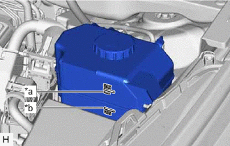
- Adjust the brake fluid level of the reservoir so that it is between the MIN line and fluid level support line.
*a Fluid Level Support Line *b MIN Line - Select "Motor Deactivate" on the "ECB (Electronically Controlled Brake system) Utility" screen.
Chassis > Brake/EPB > Utility
Tester Display ECB Utility - Perform "Motor Deactivate" according to the display on the GTS.
- Depress the brake pedal 40 times or more to return all the fluid in the accumulator back to the reservoir.
HINT:
A buzzer may sound due to low accumulator pressure. As this is not a malfunction, continue the procedure.
- Check that the brake pedal is firm.
- Check the values output from "Stroke Sensor" and "Stroke Sensor2" by depressing the brake pedal.
Chassis > Brake Booster > Data List
Tester Display Stroke Sensor Chassis > Brake/EPB > Data List
Tester Display Stroke Sensor2 Standard Result
Pedal Effort Stroke Sensor
(V)Stroke Sensor2
(V)Front Left Wheel Hydraulic Pressure Front Right Wheel Hydraulic Pressure 200 N (20 kgf, 45.0 lbf) 1.55 to 2.25 2.75 to 3.45 0.00 to 2.88 MPa (0.0 to 29.4 kgf/cm2 , 0 to 418 psi) 0.00 to 2.88 MPa (0.0 to 29.4 kgf/cm2 , 0 to 418 psi) 500 N (51 kgf, 112.4 lbf) 1.97 to 2.67 2.33 to 3.03 1.13 to 5.13 MPa (11.5 to 52.3 kgf/cm2 , 164 to 744 psi) 1.13 to 5.13 MPa (11.5 to 52.3 kgf/cm2 , 164 to 744 psi) Standard Result
Pedal Effort Stroke Sensor
(V)Stroke Sensor2
(V)Rear Left Wheel Hydraulic Pressure Rear Right Wheel Hydraulic Pressure 200 N (20 kgf, 45.0 lbf) 1.55 to 2.25 2.75 to 3.45 0.00 to 2.88 MPa (0.0 to 29.4 kgf/cm2 , 0 to 418 psi) 0.00 to 2.88 MPa (0.0 to 29.4 kgf/cm2 , 0 to 418 psi) 500 N (51 kgf, 112.4 lbf) 1.97 to 2.67 2.33 to 3.03 1.13 to 5.13 MPa (11.5 to 52.3 kgf/cm2 , 164 to 744 psi) 1.13 to 5.13 MPa (11.5 to 52.3 kgf/cm2 , 164 to 744 psi) HINT:
Check the performance of the brake booster with master cylinder assembly by comparing the pedal force with the value of the LSPV gauge and each stroke sensor. If there is a problem, determine the state of the brake booster with master cylinder assembly by using these results together with the results from inspecting the brake pedal stroke sensor.
- Remove the pedal effort gauge and SST, and bleed the brake system.
Refer to BLEEDING [12/2019 - ]
- Check the value output from "Accumulator Pressure".
Chassis > Brake Booster > Data List
Tester Display Accumulator Pressure Standard Result
15 to 21 MPa
- Clear the DTCs.
Refer to DTC CHECK / CLEAR [12/2019 - ]
- Inspect and adjust the brake pedal height.
- Check the auxiliary battery voltage.
- INSPECT STROKE SIMULATOR (BRAKE BOOSTER WITH MASTER CYLINDER ASSEMBLY)
- Check the auxiliary battery voltage.
Standard Voltage
11 to 14 V (while the ignition switch is off)
- Set a pedal effort gauge.
- Set a pedal effort gauge.
- Move the shift lever to P and apply the parking brake.
- Clear the DTCs.
Refer to DTC CHECK / CLEAR [12/2019 - ]
- Check operation with brake boost.
- Depress the brake pedal 4 or 5 times.
- Check the values output from "Stroke Sensor" and "Stroke Sensor2" by depressing the brake pedal.
Chassis > Brake Booster > Data List
Tester Display Stroke Sensor Chassis > Brake/EPB > Data List
Tester Display Stroke Sensor2 Standard Voltage
Pedal Effort Stroke Sensor
(V)Stroke Sensor2
(V)50 N (5 kgf, 11.2 lbf) 1.20 to 1.90 3.10 to 3.80 100 N (10 kgf, 22.5 lbf) 1.42 to 2.16 2.88 to 3.58 150 N (15 kgf, 33.7 lbf) 1.61 to 2.31 2.69 to 3.39
- Check the auxiliary battery voltage.