DTC C169D-87: Side Camera (Right) Image Signal Missing Message [10/2022 - ]: Procedure
- CHECK FOR DTCs
- Using the GTS, check for DTCs and proceed to the respective link below.
Chassis > Circumference Monitoring Camera Control Module > Trouble Codes
Result
Result Proceed to C169D-87 is output A DTC C169D-87 and either C1622-87, C1681-87, C168E-87 are output B
Result:
B
PROCEED TO THE RESPECTIVE PROCEDURE
Refer to Image from Camera for Panoramic View Monitor is Abnormal [10/2022 - ]
Result:
A
See step 2
- Using the GTS, check for DTCs and proceed to the respective link below.
- CHECK HARNESS AND CONNECTOR (PARKING ASSIST ECU - OUTER REAR VIEW MIRROR ASSEMBLY RH)
Pre-procedure1
- Disconnect the H126 parking assist ECU connector.
- Disconnect the J33 outer rear view mirror assembly RH connector.
Procedure1
- Measure the resistance according to the value(s) in the table below.
Standard Resistance
Tester Connection Condition Specified Condition H126-1 (CB+) - J33-2 (CB+) Always Below 1 Ω H126-3 (CV+) - J33-4 (CV+) Always Below 1 Ω H126-4 (CV-) - J33-3 (CV-) Always Below 1 Ω H126-2 (CGND) - J33-1 (CGND) Always Below 1 Ω H126-5 (SGND) - J33-5 (SGND) Always Below 1 Ω H126-1 (CB+) or J33-2 (CB+) - Body ground Always 10 kΩ or higher H126-3 (CV+) or J33-4 (CV+) - Body ground Always 10 kΩ or higher H126-4 (CV-) or J33-3 (CV-) - Body ground Always 10 kΩ or higher H126-2 (CGND) or J33-1 (CGND) - Body ground Always 10 kΩ or higher H126-5 (SGND) or J33-5 (SGND) - Body ground Always 10 kΩ or higher Result
Proceed to OK NG Post-procedure1
- None
Result:
NG
REPAIR OR REPLACE HARNESS OR CONNECTOR
Result:
OK
See step 3
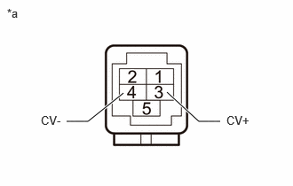
- CHECK PARKING ASSIST ECU (CV+, CV-)
Pre-procedure1
- Disconnect the H126 parking assist ECU connector.
*a Component without harness connected
(Parking Assist ECU)Procedure1
- Measure the resistance according to the value(s) in the table below.
Standard Resistance
Tester Connection Condition Specified Condition 3 (CV+) - Body ground Always 10 kΩ or higher 4 (CV-) - Body ground Always 10 kΩ or higher Result
Proceed to OK NG Post-procedure1
- None
Result:
NG
REPLACE PARKING ASSIST ECU
Refer to REMOVAL [10/2022 - 11/2023] , or refer to REMOVAL [11/2023 - ]
Result:
OK
See step 4
- Disconnect the H126 parking assist ECU connector.
- CHECK PARKING ASSIST ECU (CB+, CGND)
Pre-procedure1
- Disconnect the outer rear view mirror assembly RH connector.
Procedure1
- Measure the resistance according to the value(s) in the table below.
Standard Resistance
Tester Connection Condition Specified Condition J33-1 (CGND) - Body ground Always Below 1 Ω - Measure the voltage according to the value(s) in the table below.
Standard Voltage
Tester Connection Switch Condition Specified Condition J33-2 (CB+) - J33-1 (CGND) Ignition switch ON 7.5 to 8.5 V Result
Proceed to OK NG Post-procedure1
- None
Result:
NG
REPLACE PARKING ASSIST ECU
Refer to REMOVAL [10/2022 - 11/2023] , or refer to REMOVAL [11/2023 - ]
Result:
OK
See step 5
- Disconnect the outer rear view mirror assembly RH connector.
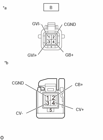
- INSPECT OUTER REAR VIEW MIRROR ASSEMBLY RH
Pre-procedure1
- Disconnect the side television camera assembly RH connector.
*a Front view of wire harness connector
(to Side Television Camera Assembly RH)*b Component without harness connected
(Outer Rear View Mirror Assembly RH) - Disconnect the outer rear view mirror assembly RH connector.
Procedure1
- Measure the resistance according to the value(s) in the table below.
Standard Resistance
Tester Connection Condition Specified Condition 2 (CB+) - B-4 (GB+) Always Below 1 Ω 4 (CV+) - B-3 (GVI+) Always Below 1 Ω 3 (CV-) - B-1 (GVI-) Always Below 1 Ω 1 (CGND) - B-2 (CGND) Always Below 1 Ω 2 (CB+) or B-4 (GB+) - Body ground Always 10 kΩ or higher 4 (CV+) or B-3 (GVI+) - Body ground Always 10 kΩ or higher 3 (CV-) or B-1 (GVI-) - Body ground Always 10 kΩ or higher 1 (CGND) or B-2 (CGND) - Body ground Always 10 kΩ or higher Result
Proceed to OK NG - None
Post-procedure1
Result:
NG
REPLACE OUTER REAR VIEW MIRROR ASSEMBLY RH
Refer to REMOVAL [12/2019 - 11/2023] , or refer to REMOVAL [11/2023 - ]
Result:
OK
See step 6
- Disconnect the side television camera assembly RH connector.
- REPLACE SIDE TELEVISION CAMERA ASSEMBLY RH
HINT:
Refer to REMOVAL [10/2022 - 11/2023] , or refer to REMOVAL [11/2023 - ]
Result
Proceed to NEXT Result:
NEXT
See step 7
- CLEAR DTC
- Clear the DTCs.
Chassis > Circumference Monitoring Camera Control Module > Clear DTCs
Result
Proceed to NEXT
Result:
NEXT
See step 8
- Clear the DTCs.
- CHECK FOR DTC
- Check for DTCs.
Chassis > Circumference Monitoring Camera Control Module > Trouble Codes
Result
Result Proceed to C169D-87 is not output A C169D-87 is output B
Result:
A
END (SIDE TELEVISION CAMERA ASSEMBLY RH WAS DEFECTIVE)
Result:
B
REPLACE PARKING ASSIST ECU
Refer to REMOVAL [10/2022 - 11/2023] , or refer to REMOVAL [11/2023 - ]
- Check for DTCs.