Installation [10/2022 - ]: Procedure
- INSTALL VACUUM PUMP ASSEMBLY
- When reusing the vacuum pump assembly:
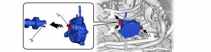
- Install the vacuum pump assembly so that the coupling teeth of the vacuum pump assembly and groove of the camshaft are engaged.
*a Coupling Teeth *b Groove NOTE:- Ensure that the vacuum pump assembly is installed securely.
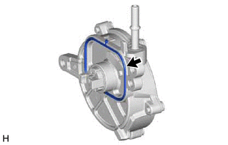
- Be careful not to pinch the No. 1 vacuum pump O-ring.
- Install the vacuum pump assembly with the 3 bolts.
Torque: 10 N.m (102 kgf/cm, 7 ft.lbf)
NOTE:- Perform the procedure by fully tightening the bolt (A), and then fully tightening the bolts (B).
- After installation, check that there are no gaps between the matching surfaces and that the vacuum pump assembly is not installed at an angle.
- CONNECT NO. 1 VACUUM HOSE CONNECTOR
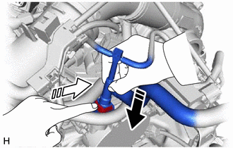
- Align the No. 1 vacuum hose connector with the vacuum pump assembly, and push them together until the retainer passes the protrusion of the vacuum pump assembly tube, then push in the retainer.

Push 
Push in NOTE:- Check that there is no foreign matter on the connecting parts.
- After connecting the No. 1 vacuum hose connector, check that the vacuum pump assembly and No. 1 vacuum hose connector are securely connected by pulling on them.
- Align the No. 1 vacuum hose connector with the vacuum pump assembly, and push them together until the retainer passes the protrusion of the vacuum pump assembly tube, then push in the retainer.
- INSTALL COMPRESSOR INLET ELBOW SUB-ASSEMBLY
- Install the compressor inlet elbow sub-assembly.
Refer to PROCEDURE - Step 11
- Engage the clamp to connect the vacuum hose to the compressor inlet elbow sub-assembly.
- Connect the connector and 2 vacuum hoses to the compressor inlet elbow sub-assembly.
- Install the compressor inlet elbow sub-assembly.
- INSTALL AIR CLEANER CAP WITH AIR CLEANER HOSE
- INSTALL NO. 1 ENGINE COVER SUB-ASSEMBLY
Refer to PROCEDURE - Step 56 [10/2022 - 11/2023] , or refer to PROCEDURE - Step 56 [11/2023 - ]
- INSTALL BATTERY
Refer to INSTALLATION [10/2022 - 11/2023] , or refer to INSTALLATION [11/2023 - ]
- INSPECT VACUUM PUMP OPERATION
Refer to ON-VEHICLE INSPECTION [10/2022 - ]