Disassembly [12/2019 - 10/2022]: Procedure
- REMOVE TRANSMISSION CONTROL SHAFT LEVER
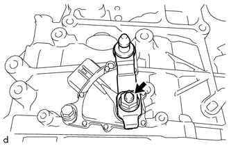
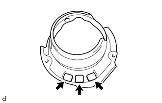
- REMOVE PARK/NEUTRAL POSITION SWITCH ASSEMBLY
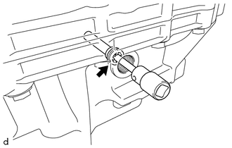
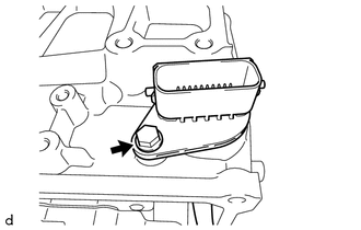
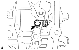
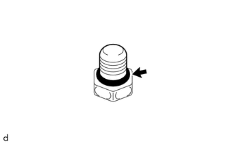
- REMOVE REFILL PLUG
- REMOVE OVERFLOW PLUG
- REMOVE NO. 1 TRANSMISSION OIL FILLER TUBE
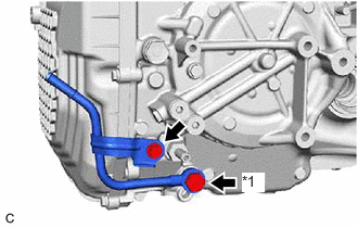
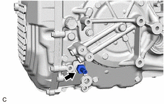
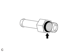
- REMOVE OIL COOLER UNION SUB-ASSEMBLY
- REMOVE OIL COOLER OUTLET UNION OR ELBOW
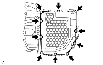
- REMOVE TRANSMISSION CASE SIDE COVER
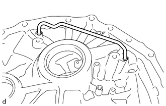
- REMOVE TRANSMISSION WIRE (w/o Stop And Start System)
- Disengage the clamp to disconnect the transmission wire from the solenoid lock plate.
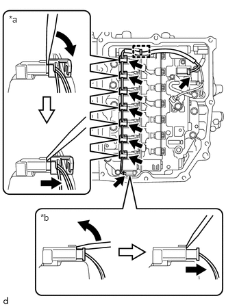
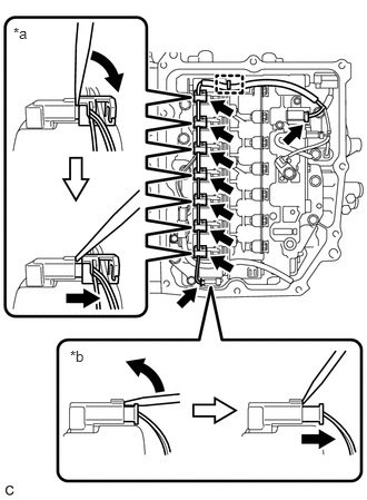
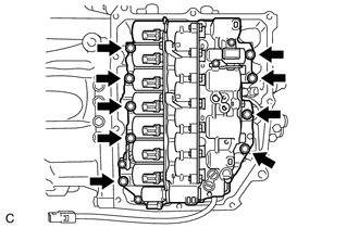
*a Connector (A) *b Connector (B) - Disconnect the 9 solenoid valve connectors.
HINT:
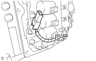
- Using a screwdriver, disconnect the solenoid valve connector (A) using the procedure shown in the illustration.
- Using a screwdriver, disconnect the solenoid valve connector (B) using the procedure shown in the illustration.
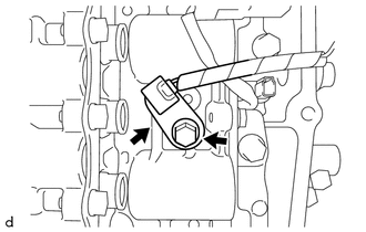
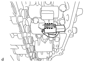
- Remove the bolt and temperature sensor clamp and separate the temperature sensor from the transmission valve body assembly.
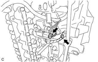
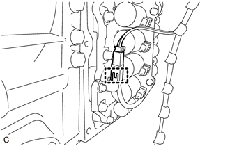
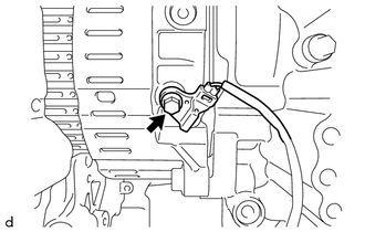
- Disconnect the transmission revolution sensor (NT) connector and transmission revolution sensor (NC) connector.
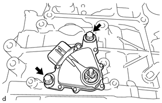
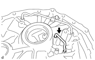
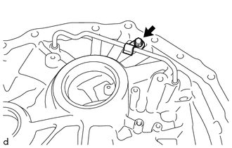
- Remove the bolt and transmission wire from the automatic transmission case sub-assembly.
- Disengage the clamp to disconnect the transmission wire from the solenoid lock plate.
- REMOVE TRANSMISSION WIRE (w/ Stop And Start System)
- Disengage the clamp to disconnect the transmission wire from the solenoid lock plate.
*a Connector (A) *b Connector (B) - Disconnect the 9 solenoid valve connectors.
HINT:
- Using a screwdriver, disconnect the solenoid valve connector (A) using the procedure shown in the illustration.
- Using a screwdriver, disconnect the solenoid valve connector (B) using the procedure shown in the illustration.
- Disengage the wire harness clamp to disconnect the transmission wire (oil pump with solenoid assembly).
- Disconnect the transmission wire connector.
- Disengage the clamp to disconnect the transmission wire (oil pump with solenoid assembly) from the solenoid lock plate.
- Remove the bolt and temperature sensor clamp and separate the temperature sensor from the transmission valve body assembly.
- Disconnect the transmission revolution sensor (NT) connector and transmission revolution sensor (NC) connector.
- Remove the bolt and transmission wire from the automatic transmission case sub-assembly.
- Disengage the clamp to disconnect the transmission wire from the solenoid lock plate.
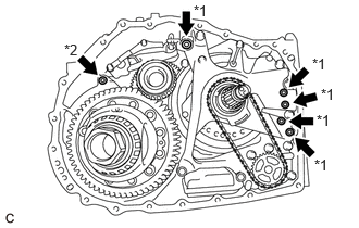
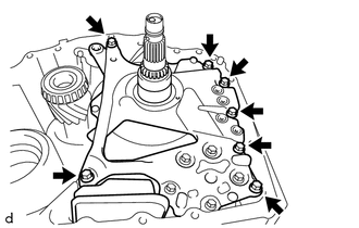
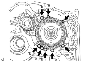
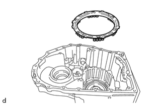
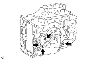
- REMOVE TRANSMISSION VALVE BODY ASSEMBLY (w/o Stop And Start System)
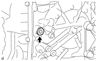
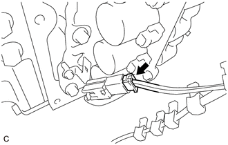
- Disengage the clamp to disconnect the transmission revolution sensor (NC) wire connector.
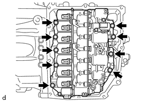
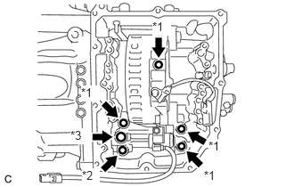
- Remove the 9 bolts and transmission valve body assembly from the automatic transaxle case sub-assembly.
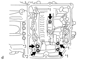
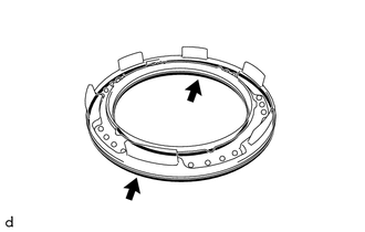
- Remove the 2 transaxle case gaskets from the automatic transaxle case sub-assembly.
*1 Transaxle Case Gasket *2 No. 1 Front Oil Pump Cover Gasket *3 No. 2 Front Oil Pump Cover Gasket - Remove the transaxle case gasket from the counter drive gear sub-assembly.
- Remove the No. 1 front oil pump cover gasket from the front oil pump assembly.
- Remove the No. 2 front oil pump cover gasket from the front oil pump assembly.
- Disengage the clamp to disconnect the transmission revolution sensor (NC) wire connector.
- REMOVE TRANSMISSION VALVE BODY ASSEMBLY (w/ Stop And Start System)
- Disengage the clamp to disconnect the transmission revolution sensor (NC) wire connector.
- Remove the 9 bolts and transmission valve body assembly from the automatic transaxle case sub-assembly.
- Remove the 2 transaxle case gaskets from the automatic transaxle case sub-assembly.
*1 Transaxle Case Gasket *2 No. 1 Front Oil Pump Cover Gasket *3 No. 2 Front Oil Pump Cover Gasket - Remove the transaxle case gasket from the counter drive gear sub-assembly.
- Remove the transaxle case gasket from the front oil pump assembly.
- Remove the No. 1 front oil pump cover gasket from the front oil pump assembly.
- Remove the No. 2 front oil pump cover gasket from the front oil pump assembly.
- Disengage the clamp to disconnect the transmission revolution sensor (NC) wire connector.
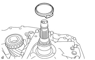
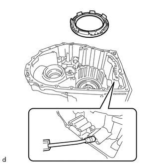
- REMOVE TRANSMISSION REVOLUTION SENSOR (NT)
- REMOVE TRANSMISSION REVOLUTION SENSOR (NC)
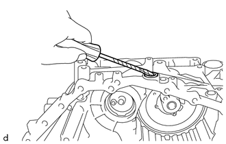
- INSPECT INPUT SHAFT END PLAY
See step 12
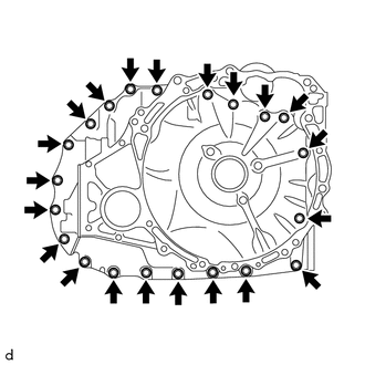
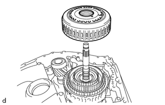
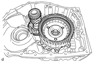
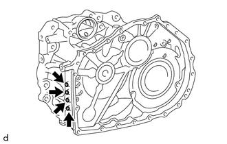
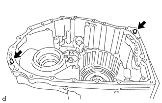
- REMOVE TRANSAXLE HOUSING
- Remove the 21 bolts.
- Using a plastic hammer, tap on the circumference of the transaxle housing to remove it from the automatic transaxle case sub-assembly.
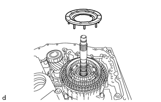
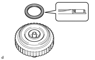
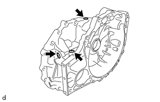
- Remove the 5 transaxle case gaskets from the front oil pump assembly.
*1 Transaxle Case Gasket *2 O-ring - Remove the O-ring from the automatic transaxle case sub-assembly.
- Remove the 21 bolts.
- REMOVE TRANSAXLE HOUSING OIL SEPARATOR
- REMOVE TRANSMISSION OIL CLEANER MAGNET
- INSPECT TRANSMISSION OIL CLEANER MAGNET
See step 1
- REMOVE DIFFERENTIAL GEAR LUBE APPLY TUBE
- REMOVE TRANSMISSION LUBE APPLY TUBE
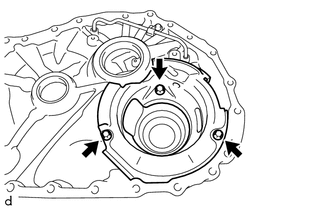
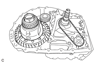
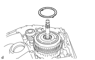
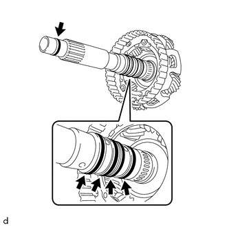
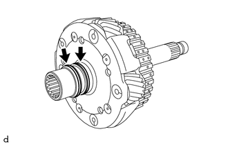
- REMOVE DIFFERENTIAL CASE ASSEMBLY
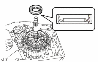
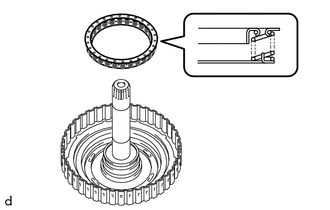
- REMOVE CLUTCH DRUM OIL SEAL RING
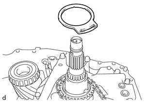
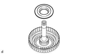
- REMOVE OIL PUMP SPROCKET FRONT THRUST WASHER
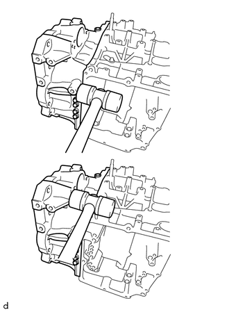
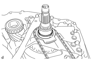
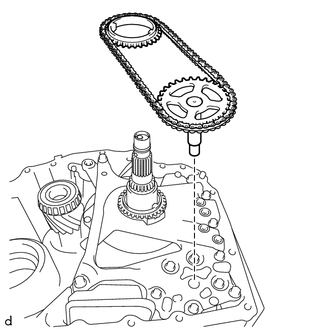
- REMOVE TRANSMISSION DRIVE CHAIN
- Remove the transmission drive chain together with the transmission oil pump drive sprocket and oil pump drive shaft sub-assembly from the front oil pump assembly.NOTE:
To avoid damaging the bush of the front oil pump assembly, remove the transmission drive chain, transmission oil pump drive sprocket and oil pump drive shaft sub-assembly horizontally relative to the front oil pump assembly.
- Remove the transmission drive chain together with the transmission oil pump drive sprocket and oil pump drive shaft sub-assembly from the front oil pump assembly.
- REMOVE OIL PUMP SPROCKET REAR THRUST WASHER
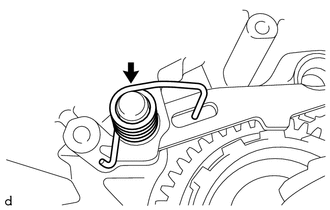
- REMOVE MANUAL DETENT SPRING SUB-ASSEMBLY
- REMOVE FRONT OIL PUMP ASSEMBLY NOTE:
To avoid damaging the front oil pump assembly and transmission valve body assembly, when removing the front oil pump assembly, first remove the transmission valve body assembly.
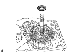
- REMOVE PLANETARY CARRIER THRUST WASHER
- REMOVE C-3 AND C-4 CLUTCH ASSEMBLY
- INSPECT CLEARANCE OF C-3 CLUTCH
See step 13
- INSPECT CLEARANCE OF C-4 CLUTCH
See step 14
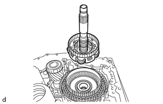
- REMOVE NO. 2 PLANETARY CARRIER THRUST WASHER
- REMOVE PLANETARY SUN GEAR
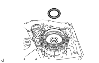
- REMOVE NO. 9 THRUST BEARING RACE
- REMOVE THRUST NEEDLE ROLLER BEARING
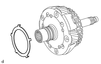
- REMOVE NO. 8 THRUST BEARING RACE
- REMOVE FRONT PLANETARY GEAR ASSEMBLY
- REMOVE THRUST NEEDLE ROLLER BEARING
- REMOVE NO. 7 THRUST BEARING RACE
- INSPECT FRONT PLANETARY GEAR ASSEMBLY
See step 10
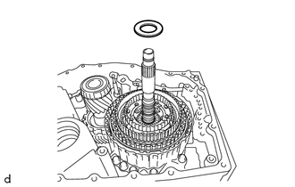
- REMOVE INPUT SHAFT OIL SEAL RING
- REMOVE REAR INPUT SHAFT OIL SEAL RING
- REMOVE FRONT PLANETARY RING GEAR
- Remove the front planetary ring gear with front planetary ring gear flange from the C-1 clutch assembly.
- Using a screwdriver with its tip wrapped with protective tape, remove the snap ring from the front planetary ring gear.NOTE:
Be careful not to damage the front planetary ring gear and front planetary ring gear flange.
- Remove the front planetary ring gear flange from the front planetary ring gear.
- Remove the front planetary ring gear with front planetary ring gear flange from the C-1 clutch assembly.
- REMOVE THRUST NEEDLE ROLLER BEARING
- REMOVE NO. 6 THRUST BEARING RACE
- REMOVE C-1 CLUTCH ASSEMBLY
- INSPECT CLEARANCE OF C-1 CLUTCH
See step 15
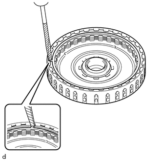
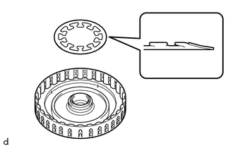
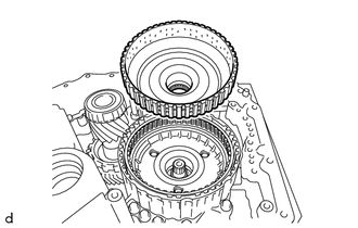
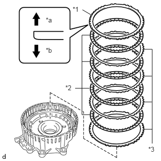
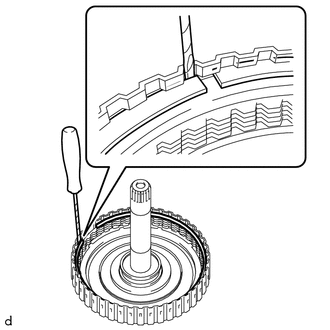
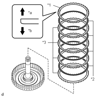
- REMOVE FRONT CLUTCH DISC
- Using a screwdriver with its tip wrapped with protective tape, remove the snap ring from the clutch drum sub-assembly.NOTE:
Be careful not to damage the clutch drum sub-assembly.
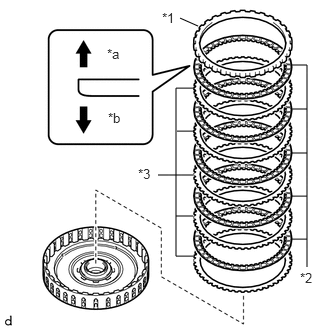
- Remove the forward clutch flange, 5 front clutch discs and 5 forward multiple disc clutch plates from the clutch drum sub-assembly.
*1 Forward Clutch Flange *2 Front Clutch Disc *3 Forward Multiple Disc Clutch Plate *a Snap Ring Side *b Front Clutch Disc Side
- Using a screwdriver with its tip wrapped with protective tape, remove the snap ring from the clutch drum sub-assembly.
- INSPECT FRONT CLUTCH DISC
See step 2
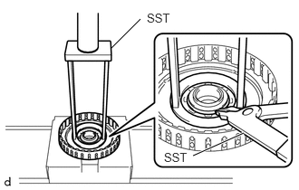
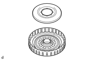
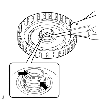
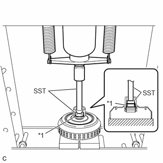
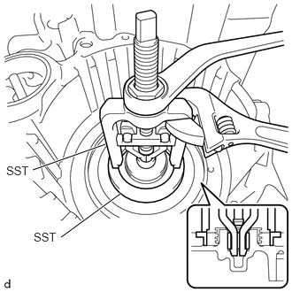
- REMOVE NO. 1 CLUTCH BALANCER
- Place SST on the No. 1 clutch balancer and compress the rear clutch piston return compression spring with a press.
- SST: 09387-00020
NOTE:Do not compress the rear clutch piston return compression spring excessively.
- Using SST, remove the snap ring from the clutch drum sub-assembly.
- SST: 09350-30020
- 09350-07070
- SST: 09350-30020
- Remove the No. 1 clutch balancer from the forward clutch piston.
- Place SST on the No. 1 clutch balancer and compress the rear clutch piston return compression spring with a press.
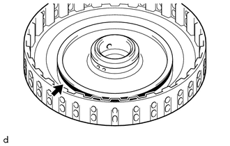
- REMOVE REAR CLUTCH PISTON RETURN COMPRESSION SPRING
- REMOVE FORWARD CLUTCH PISTON
- Apply compressed air (392 kPa (4.0 kgf/cm2
, 57 psi)) to the ATF hole of the clutch drum sub-assembly to remove the forward clutch piston from the clutch drum sub-assembly.NOTE:
- Applying compressed air may cause the forward clutch piston to jump out. When removing the forward clutch piston, hold it by hand using a piece of cloth.
- Be careful as ATF may spray when applying compressed air.
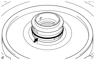
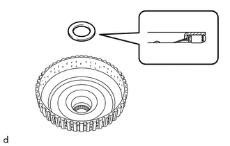
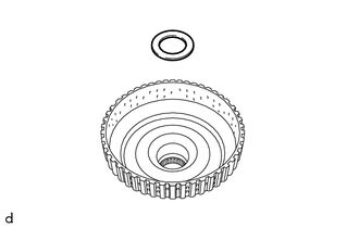
- Remove the O-ring from the clutch drum sub-assembly.
- Remove the D-ring from the clutch drum sub-assembly.
- As shown in the illustration, using a press and SST, remove the needle roller bearing from the clutch drum sub-assembly.
*1 Needle Roller Bearing - SST: 09950-60011
- 09951-00310
- SST: 09950-70010
- 09951-07100
HINT:
Only perform this operation when replacing the needle roller bearing.
- SST: 09950-60011
- Apply compressed air (392 kPa (4.0 kgf/cm2
, 57 psi)) to the ATF hole of the clutch drum sub-assembly to remove the forward clutch piston from the clutch drum sub-assembly.
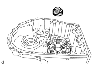
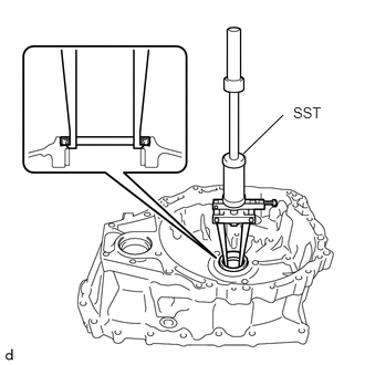
- REMOVE SUN GEAR INPUT HUB SUB-ASSEMBLY
- REMOVE THRUST NEEDLE ROLLER BEARING
- REMOVE NO. 5 THRUST BEARING RACE
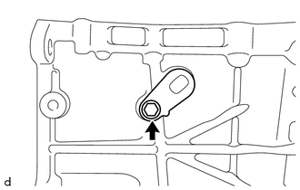
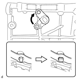
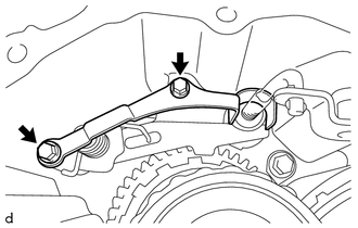
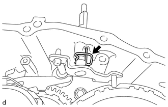
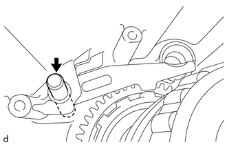
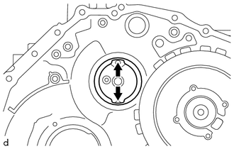
- REMOVE MANUAL VALVE LEVER SHAFT SUB-ASSEMBLY
- Remove the bolt.
- Align the cutouts of the manual valve lever sub-assembly and manual valve lever shaft sub-assembly, and remove the manual valve lever shaft sub-assembly.
HINT:
Rotating the manual valve lever shaft sub-assembly to the area shown in the illustration will align the cutouts.
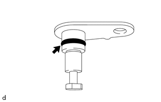
- Remove the O-ring from the manual valve lever shaft sub-assembly.
- Remove the bolt.
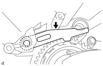
- REMOVE MANUAL VALVE LEVER SUB-ASSEMBLY
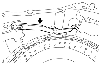
- REMOVE PAWL STOPPER PLATE
- REMOVE MANUAL VALVE LEVER SHAFT RETAINER SPRING
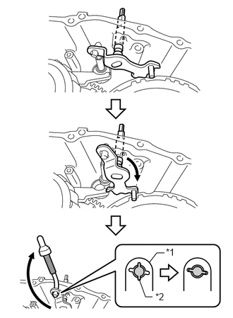
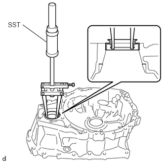
- REMOVE PARKING LOCK ROD SUB-ASSEMBLY
- Move the manual valve lever shaft sub-assembly and parking lock rod sub-assembly as shown in the illustration, and remove the parking lock rod sub-assembly.
*1 Manual Valve Lever Shaft Sub-assembly *2 Parking Lock Rod Sub-assembly HINT:
Align the cutouts of the parking lock rod sub-assembly and manual valve lever shaft sub-assembly and remove the parking lock rod sub-assembly.
- Move the manual valve lever shaft sub-assembly and parking lock rod sub-assembly as shown in the illustration, and remove the parking lock rod sub-assembly.
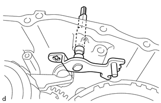
- REMOVE MANUAL VALVE LEVER SHAFT SUB-ASSEMBLY
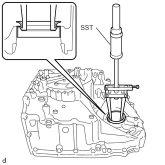
- REMOVE PARKING LOCK PAWL TORSION SPRING
- REMOVE PARKING LOCK PAWL SHAFT
- REMOVE PARKING LOCK PAWL
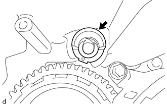
- REMOVE PARKING LOCK SLEEVE
- INSPECT CLEARANCE OF B-1 BRAKE
See step 16
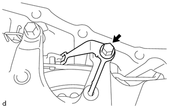
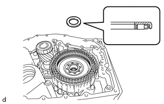
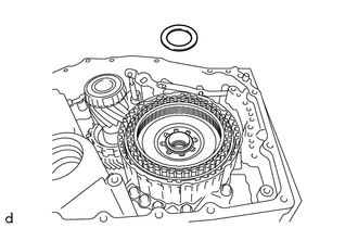
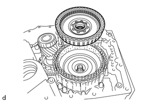
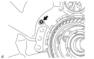
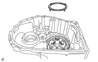
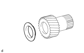
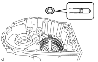
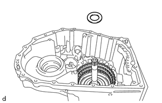
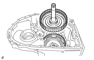
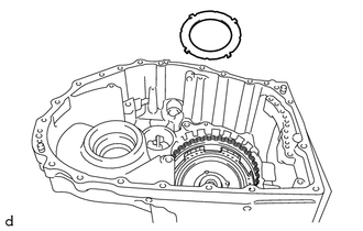
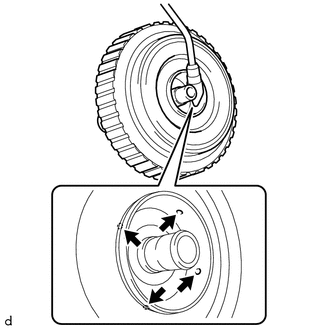
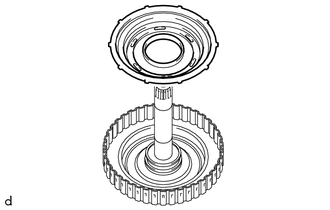
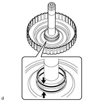
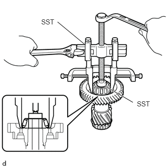
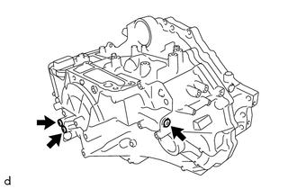
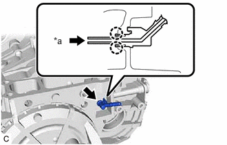
- REMOVE COUNTER DRIVE GEAR SUB-ASSEMBLY
- Using a T50 "TORX" socket wrench, remove the 2 bolts (A) from the counter drive gear sub-assembly.
*a Bolt A *b Bolt B - Remove the 6 bolts (B) from the counter drive gear sub-assembly.
- Remove the counter drive gear sub-assembly together with the pinion and counter driven gear sub-assembly from the automatic transaxle case sub-assembly.
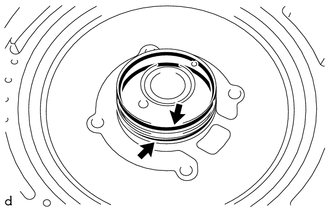
- Remove the O-ring from the automatic transaxle case sub-assembly.
- Using a T50 "TORX" socket wrench, remove the 2 bolts (A) from the counter drive gear sub-assembly.
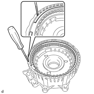
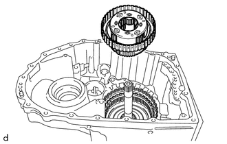
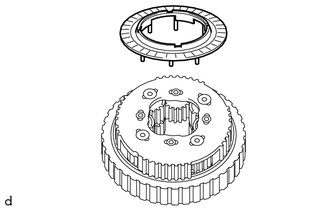
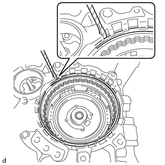
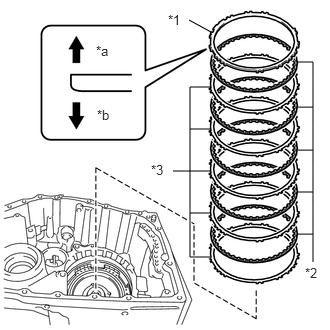
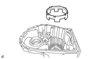
- REMOVE NO. 1 BRAKE DISC
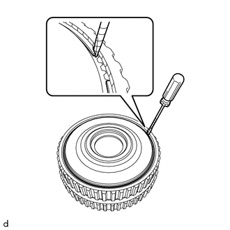
- Using a screwdriver with its tip wrapped with protective tape, remove the snap ring from the counter drive gear sub-assembly.NOTE:
Be careful not to damage the counter drive gear sub-assembly.
- Remove the No. 1 brake flange, 4 No. 1 brake discs and 4 No. 1 brake plates from the counter drive gear sub-assembly.
*1 No. 1 Brake Flange *2 No. 1 Brake Disc *3 No. 1 Brake Plate *a Snap Ring Side *b No. 1 Brake Disc Side
- Using a screwdriver with its tip wrapped with protective tape, remove the snap ring from the counter drive gear sub-assembly.
- INSPECT NO. 1 BRAKE DISC
See step 4
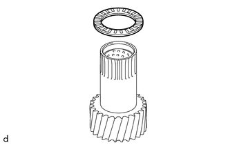
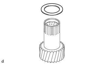
- REMOVE NO. 3 PLANETARY CARRIER THRUST WASHER
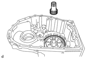
- REMOVE PLANETARY SUN GEAR SUB-ASSEMBLY
- INSPECT PLANETARY SUN GEAR SUB-ASSEMBLY
See step 8
- REMOVE REAR PLANETARY SUN GEAR SUB-ASSEMBLY
- REMOVE REAR PLANETARY GEAR ASSEMBLY
- REMOVE NO. 4 PLANETARY CARRIER THRUST WASHER
- INSPECT REAR PLANETARY GEAR ASSEMBLY
See step 11
- REMOVE NO. 4 THRUST BEARING RACE
- REMOVE THRUST NEEDLE ROLLER BEARING
- REMOVE THRUST BEARING RACE
- REMOVE NO. 3 THRUST BEARING RACE
- INSPECT REAR PLANETARY SUN GEAR SUB-ASSEMBLY
See step 9
- REMOVE THRUST NEEDLE ROLLER BEARING
- REMOVE NO. 2 THRUST BEARING RACE
- INSPECT CLEARANCE OF C-2 CLUTCH
See step 17
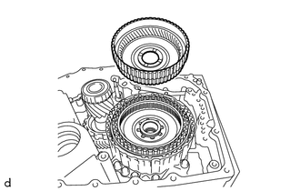
- REMOVE C-2 CLUTCH ASSEMBLY
- REMOVE THRUST NEEDLE ROLLER BEARING
- REMOVE NO. 1 THRUST BEARING RACE
- REMOVE NO. 2 CLUTCH DISC
- Using a screwdriver with its tip wrapped with protective tape, remove the snap ring from the intermediate shaft sub-assembly.NOTE:
Be careful not to damage the intermediate shaft sub-assembly.
- Remove the direct clutch flange, 4 No. 2 clutch discs and 4 No. 2 clutch plates from the intermediate shaft sub-assembly.
*1 Direct Clutch Flange *2 No. 2 Clutch Disc *3 No. 2 Clutch Plate *a Snap Ring Side *b No. 2 Clutch Disc Side
- Using a screwdriver with its tip wrapped with protective tape, remove the snap ring from the intermediate shaft sub-assembly.
- INSPECT NO. 2 CLUTCH DISC
See step 3
- REMOVE C-2 CLUTCH BALANCER
- Place SST on the C-2 clutch balancer and compress the clutch return spring sub-assembly with a press.
- SST: 09387-00020
NOTE:Do not compress the clutch return spring sub-assembly excessively.
- Using SST, remove the snap ring from the intermediate shaft sub-assembly.
- SST: 09350-30020
- 09350-07070
- SST: 09350-30020
- Remove the C-2 clutch balancer from the intermediate shaft sub-assembly.
- Place SST on the C-2 clutch balancer and compress the clutch return spring sub-assembly with a press.
- REMOVE CLUTCH RETURN SPRING SUB-ASSEMBLY
- INSPECT CLUTCH RETURN SPRING SUB-ASSEMBLY
See step 6
- REMOVE C-2 CLUTCH PISTON
- Apply compressed air (392 kPa (4.0 kgf/cm2
, 57 psi)) to the ATF hole of the intermediate shaft sub-assembly.NOTE:
- Applying compressed air may cause the C-2 clutch piston to jump out. When removing the C-2 clutch piston, hold it by hand using a piece of cloth.
- Be careful as ATF may spray when applying compressed air.
- Remove the C-2 clutch piston from the intermediate shaft sub-assembly.
- Remove the 2 O-rings from the intermediate shaft sub-assembly.
- Apply compressed air (392 kPa (4.0 kgf/cm2
, 57 psi)) to the ATF hole of the intermediate shaft sub-assembly.
- REMOVE DIRECT CLUTCH DRUM OIL SEAL RING
- INSPECT CLEARANCE OF B-2 BRAKE
See step 18
- REMOVE 2ND BRAKE DISC
- Using a screwdriver with its tip wrapped with protective tape, remove the snap ring from the automatic transaxle case sub-assembly.NOTE:
Be careful not to damage the automatic transaxle case sub-assembly.
- Remove the 2nd brake flange, 5 2nd brake discs and 5 2nd brake plates from the automatic transaxle case sub-assembly.
*1 2nd Brake Flange *2 2nd Brake Disc *3 2nd Brake Plate *a Snap Ring Side *b 2nd Brake Disc Side
- Using a screwdriver with its tip wrapped with protective tape, remove the snap ring from the automatic transaxle case sub-assembly.
- INSPECT 2ND BRAKE DISC
See step 5
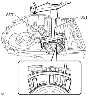
- REMOVE NO. 2 1ST AND REVERSE BRAKE PISTON
- REMOVE 1ST AND REVERSE BRAKE RETURN SPRING SUB-ASSEMBLY
- Place SST on the 1st and reverse brake return spring sub-assembly and compress it with a press.
- SST: 09380-60011
- 09381-06020
- 09381-06050
- 09381-06060
- 09381-06100
- 09381-06110
- SST: 09950-70010
- 09951-07200
NOTE:Do not compress the 1st and reverse brake return spring sub-assembly excessively.
- SST: 09380-60011
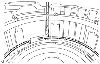
- Using a screwdriver with its tip wrapped with protective tape, remove the snap ring from the automatic transaxle case sub-assembly.NOTE:
Be careful not to damage the automatic transaxle case sub-assembly.
- Remove the 1st and reverse brake return spring sub-assembly from the automatic transaxle case sub-assembly.
- Place SST on the 1st and reverse brake return spring sub-assembly and compress it with a press.
- INSPECT 1ST AND REVERSE BRAKE RETURN SPRING SUB-ASSEMBLY
See step 7
- REMOVE 1ST AND REVERSE BRAKE PISTON
- REMOVE NEEDLE ROLLER BEARING
- REMOVE MANUAL VALVE LEVER SHAFT OIL SEAL
- REMOVE FRONT TRANSAXLE CASE OIL SEAL
- REMOVE FRONT DRIVE SHAFT OIL SEAL RH
- REMOVE FRONT DRIVE SHAFT OIL SEAL LH
- REMOVE NEEDLE ROLLER BEARING
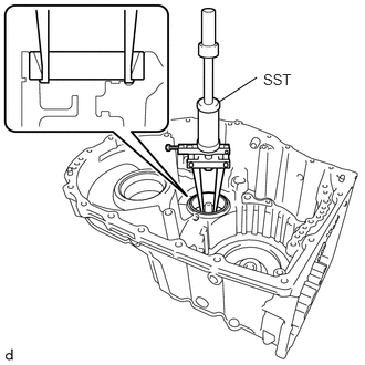
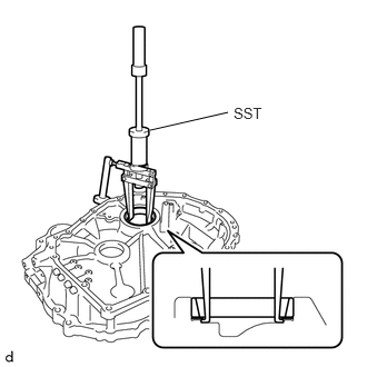
- REMOVE COUNTER DRIVEN GEAR REAR TAPERED ROLLER BEARING (OUTER RACE)
- Using SST, remove the counter driven gear rear tapered roller bearing (outer race) from the automatic transaxle case sub-assembly.
- SST: 09308-36010
NOTE:Be careful not to damage the automatic transaxle case sub-assembly.
HINT:
Align the claw of SST with the indentation of the automatic transaxle case sub-assembly when removing the parts.
- Using SST, remove the counter driven gear rear tapered roller bearing (outer race) from the automatic transaxle case sub-assembly.
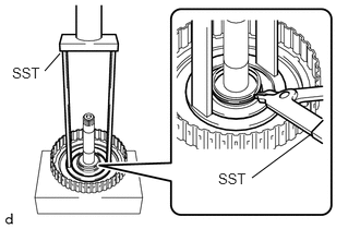
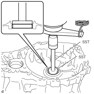
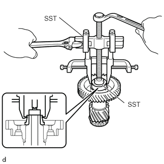
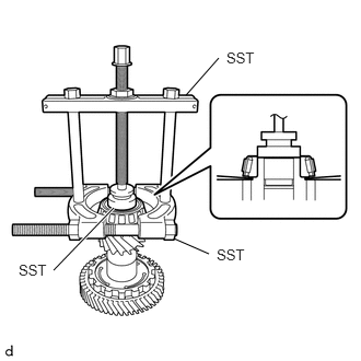
- REMOVE COUNTER DRIVEN GEAR REAR TAPERED ROLLER BEARING (INNER RACE)
- Using SST, remove the counter driven gear rear tapered roller bearing (inner race) from the pinion and counter driven gear sub-assembly.
- SST: 09950-40011
- 09951-04010
- 09952-04010
- 09953-04030
- 09954-04010
- 09955-04011
- 09957-04010
- 09958-04011
- SST: 09950-60011
- 09951-00310
NOTE:Because SST is attached to the roller portion, there is a possibility that the roller portion could break and SST could come off before the counter driven gear rear tapered roller bearing (inner race) comes off.
- SST: 09950-40011
- If the roller portion breaks and SST comes off, reattach SST to the inner race in the position shown in the illustration, and continue removing the parts.
- SST: 09950-40011
- 09951-04010
- 09952-04010
- 09953-04030
- 09954-04010
- 09955-04011
- 09957-04010
- 09958-04011
- SST: 09950-60011
- 09951-00310
- SST: 09950-40011
- Using SST, remove the counter driven gear rear tapered roller bearing (inner race) from the pinion and counter driven gear sub-assembly.
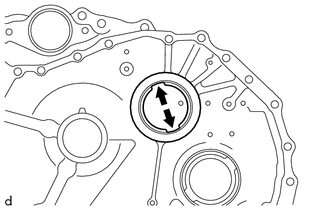
- REMOVE COUNTER DRIVEN GEAR FRONT TAPERED ROLLER BEARING (OUTER RACE)
- Using SST, remove the counter driven gear front tapered roller bearing (outer race) and pinion and counter driven gear shim from the transaxle housing.
- SST: 09308-36010
NOTE:Be careful not to damage the transaxle housing.
HINT:
Align the claw of SST with the indentation of the transaxle housing when removing the parts.
- Using SST, remove the counter driven gear front tapered roller bearing (outer race) and pinion and counter driven gear shim from the transaxle housing.
- REMOVE COUNTER DRIVEN GEAR FRONT TAPERED ROLLER BEARING (INNER RACE)
- REMOVE NO. 1 TRANSAXLE CASE PLUG
- REMOVE NO. 2 TRANSAXLE CASE PLUG
- REMOVE AUTOMATIC TRANSMISSION CASE STRAIGHT PIN NOTE:
It is not necessary to remove the automatic transmission case straight pins unless they are being replaced.
- REMOVE NO. 1 BREATHER PLUG (ATM)